Tuesday, February 15, 2022

HV rescue shield for Microchip ATmega series 8-bit microcontrollers

These days I decided to play a little with ATmega328P microcontroller and it was a total disaster. I used a PICkit 4 programmer and MPLAB X + XC8 for the code writing and compiling. Then I came to the brilliant idea to use MCC (MPLAB Code Configurator) which supposedly is easy way to configure and use the different modules inside the chip. And after setting the wrong fuses for the clock source the chip was effectively bricked. It worked, but only if I put a watch crystal at 32.768 kHz as a clock source. And the programmer cannot communicate at that low frequency.

Why these chips are designed this way? The ICSP interface in PIC microcontrollers have a dedicated clock line, so the programming of the chip is independent of the his internal configuration. I start digging for solutions in the web and tried all sorts of things. Most recommended solution was to attach external clock source to XTAL1 pin. I have signal generator and tried this with different frequencies but without success.

Finally I found this excellent page ARDUINO-BASED AVR HIGH VOLTAGE PROGRAMMER and following the latest schematic I put the ATmega328Pchip on a breadboard and connected a million jumper wires to the Arduino. It worked and the chip was rescued. Of course I connected it again to the PICkit 4 and successfully bricked it again!

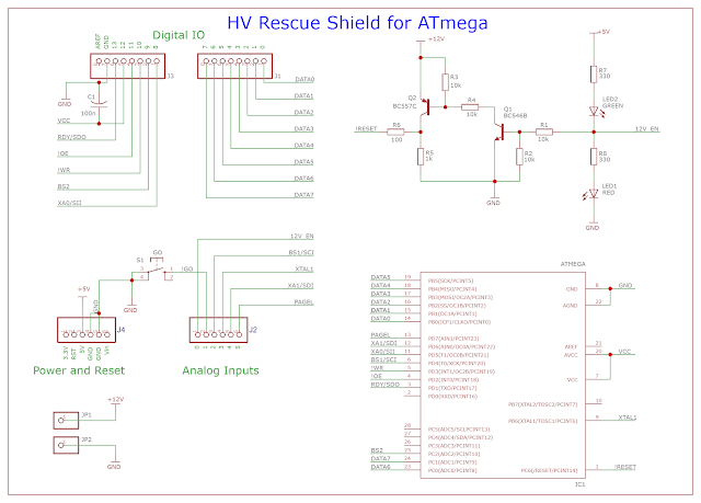
So in order to avoid dealing with jumper wires on the breadboard I get the original schematic, removed all other interfaces except the ATmega and replaced a dual PNP+NPN transistor array with discrete transistors. Also I removed the DC-DC voltage convertor because I can connect external voltage source for the 12V line. Here is the modified schematic:

And here is the finished shield for Arduino:


It worked perfectly, the chip was saved and I am ready for another bricking :)

The board was edited with EasyEDA. You can download the project files from HERE. Inside are included Gerber files. Use these on your own responsibility. The Arduino sketch for this project you can download from the original project page HERE.

Tuesday, January 25, 2022

Driving 4 digit 7-segments TM1637 display module with PIC microcontroller

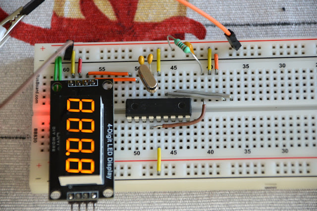
TM1637 display modules are cheap chinese modules that are offered in different colors, with digital dots or with colon. Usually these are 4 digit, but there are 6 digit modules also. I bought mine for 1.84 USD delivered. 


Tuesday, September 8, 2020

Power supply replacement for FY6900 function generator

Recently I bought an function generator from Banggood. I chose the FeelElec FY6900-60M. In the internet I found many projects for replacing the original switching power supply. The benefits are questionable, but I thought it will be fun little project to make. 

Monday, July 6, 2020

100 MHz third overtone crystal oscillator

Couple of years ago I purchased from a local store 100 MHz crystal resonator and tried several times to make a working schematic on breadboard using standard circuits I found on the internet. It never worked good enough, usually oscillating at 33.3 MHz instead of 100 MHz. Finally, I found that the crystal is third overtone type. Here some documents, that were useful for this project:

I used as a base the schematic from first document and here what I design:


Wednesday, March 20, 2019

Simple Digital Clock with PIC16F628A and DS1307 and 7-Segment LED display

In this new project I am again using PIC16F628A microcontroller. The goal is simple digital clock with 7-segment LED display and the clock will have no additional functionality - no alarm, no seconds digits, no date. The latter can be added in the software though. For the RTC chip I chose DS1307. For the LED display I used Kingbright CC56-21SRWA.


Friday, March 8, 2019

3-wire fan adapter with fake 'tach' signal

This is a quick small project that I design this evening. My wife complained about loud fan in her computer, so I purchased the quieter fan I can find in Sofia - SUNON HA80251V4-000U-999.
It's only 22 dB noise but unfortunately it is two-wire fan without yellow tach signal wire. The computer will work fine but at every startup it will beep some fan error and will require confirmation to continue.
I spend some time researching the subject and found that the tach signal is square wave signal and usually have two pulses for every rotation. So the frequency of the signal will be: F = (RPM / 60) x 2.
For example a 2000 RPM fan will have 67 Hz tach signal. 
One unusual thing about 3-wire fans is that the tach wire is connected as open collector.

The solution is very simple - small adapter board with square wave oscillator followed by a NPN transistor with open collector. The frequency of the oscillator is not that important - from 33 Hz imitating 1000 RPM fan to 200 Hz for 6000 RPM fan. I chose the classic two transistor astable multivibrator:


I soldered the components on a small piece of perfboard. The fan doesn't come with a connector but only with two strip wires, which I soldered directly to the board. On the other side I soldered standard 3-wire cable with molex connector. The adapter worked as expected - the computer recognized the fan and started without problems. I checked with HWiNFO, and the program reported around 2600 RPM for this fan.

This adapter can also be used entirely without a fan - the computer will still think there is a fan connected. Of course if your CPU burn out it will be only your fault :)