Showing posts with label PIC. Show all posts

Monday, December 19, 2022

Shaker for PCB etching

This is an old project, that was sitting in the cabinet for a very long time and I just finished it a week ago. It uses an old computer DVD drive (no one ever uses them anymore). It is completely stripped from all electronics and mechanics except for the parts that move the tray in and out. The motor inside is a simple DC motor.

The shaker uses an 8-pin microcontroller PIC16F15313 and a motor driver module based on DVR8833 chip.

There are two NO reed switches that are mounted on the case and two magnets glued on the moving tray. When one of the switches is closed by the magnet the microcontroller reverse the direction of the tray. There is also an potentiometer connected to an analog pin which control the movement speed of the tray.

The shaker is supplied with 12Vdc from an power adapter. It will work with voltages from 6V to 12V. For the microcontroller there is a 78L05 voltage regulator.

At first there was an power resistor mounted on the bottom of the aluminium sheet and connected directly to the 12V rail. The idea was to heat up the container with the etch solution, but because the container is plastic there was not much heat transfer going on and I removed it. Now I heat up the solution in the microwave oven first, and then I put the PCB in and use the shaker.

The circuit is assembled on piece of perfboard.


When using this shaker make sure the speed is not too high, because there is a risk of spilling potentially dangerous liquid around.

The code for the microcontroller is created in MPLAB X v6.08 and can be downloaded from here: Shaker_Source_Code.


Wednesday, April 6, 2022

Driving NeoPixel type ARGB LEDs with PIC

 I have ordered 10 pcs of addressable LED from Aliexpress some time ago and tested them with my Arduino boards and the library from Adafruit and they work as expected. But of course I am more a PIC guy, so I start to thinker with some PIC microcontrollers trying to drive these LEDs. And it is not easy! So the major difference between 8-bit PIC micro and a ATMEGA 328P is that the ATMEGA command rate of ATMEGA is the same as clock rate, so it has 16 MHz clock frequency and 16 MHz command rate but the PICs have command rate 4 times slower than clock frequency. So a PIC clocked at 16 MHz will have 4 MHz command rate and 32 MHz PIC will have 8 MHz command rate. In order to achieve similar performance as ATMEGA, the PIC must be clocked at 64 MHz. 

The difficulty comes from the very high frequency and the format of the output signal. The frequency of NeoPixel signal is ≈800 kHz and the "1" have 800 ns high followed by 400 ns low. The "0" is 400 ns high followed by 800 ns low. And 1 instruction of 32 MHz PIC microcontroller take 125 ns to execute. It is impossible to write a C code that can create such signal in 9-10 instructions. This is achievable only with carefully written Assembler. I had success with PIC16F1847 clocked at 32 MHz.

It was pain in the a**, because there are very little info and tutorials about writing mixed code (C and assembler) for xc8. For example I couldn't find a way to declare a variable in BANK0 in assembly code because the variables in C code evidently take precedence and occupy all the free space in BANK0 first. And it is important the variables to in the same memory bank as PORTB, because changing banks takes one additional instruction. So I has to declare the variables in the C code specifying the exact address... 

The above code has two subroutines _sendByteASM and _sendByteASM2. The first one use a cycle to check and send the bits to the serial output pin (in this case RB4). The best timing I was able to achieve this way was "0" - 375ns/875ns, "1" - 875ns/500ns. And it worked.

The second subroutine check and send every bit separately and there I was able to achieve timing much closer to the required. "0" - 375ns/875ns, "1" - 875ns/375ns. 

Then I got a more modern PIC - PIC16F15344, which have 4 very interesting modules: Configurable Logic Cell (CLC) each of which can be set as 4-input AND, AND-OR, D-type flip flop, J-K flip flop and couple of other types. Also I saw a video from the great Ben Heck where he is using the SPI output from ESP32 with some external logical chips to form the output signal compatible with NeoPixel. 

My thought was to feed the color bytes to the SPI module (configured to work at 800 kHz) and the output (clock and data) to use somehow to form impulses with different length and then combine them with CLC. The following screenshots are the settings of different modules used in this project.

The CLC1 is configured as AND-OR and the signal from the SPI is directly routed to the output. This will be needed later. 

For creating the waveforms of "0" and "1" I used the Complementary Waveform Generator (CWG). This module is used to create a signal for driving half-bridge or full bridge circuits and among other setting there can be set a dead time. So I fed the signal from CLC1 (which is a copy of SCK signal and have 50% duty cycle or 600 ns high) to the CWG module and set the dead time of the rising edge to be about 400 ns and when inverted this will be the "0". The dead time of the falling edge is set to be around 200 ns increasing low time to 800 ns and when inverted form the "1" waveform.

CLC2 is configured as 4-input AND. There I combine the inverted output from CWG1A, CLC1 and SDO from SPI to create the "0" signal:

Finally, all is combined at CLC3 which is set as AND-OR cell:

Here the inverted signal from CWG1B is "AND"-ed with the SDO signal to produce the "1" signal. Then both "0" (from CLC2) and "1" are "OR"-ed to form the final output signal which is routed to one of the pins - in my case RC4/pin6. 

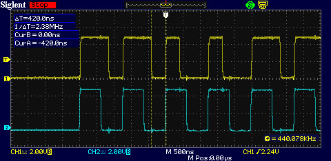
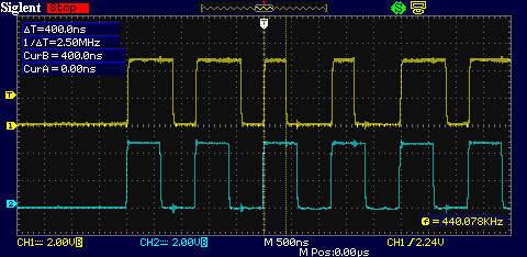
Here some scope screenshots:

The timing here is much better and the beauty of this solution is that there is no interrupts, no assembler code. All of the above is just setup of registers. I am using MPLAB Code Configurator to generate all the code and the actual work is done by the hardware modules and for sending a single byte to the NeoPixels are needed only 2 lines of code. Here is the function to send the 3 bytes for red, green and blue:

Bellow is a video demonstration how it work with the assembler code. I adapted some of Adafruit library functions for this demo: rainbow, their table for gama8 function and the function for HSV color. 

Tuesday, January 25, 2022

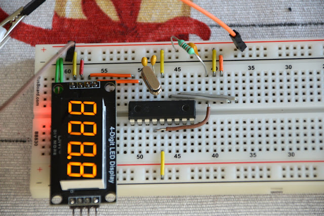
Driving 4 digit 7-segments TM1637 display module with PIC microcontroller

TM1637 display modules are cheap chinese modules that are offered in different colors, with digital dots or with colon. Usually these are 4 digit, but there are 6 digit modules also. I bought mine for 1.84 USD delivered. 


Wednesday, August 5, 2015

100MHz frequency counter

Couple of weeks ago I purchased from eBay one of these amazingly cheap an useful modules with MAX7219 LED driver and 8 digit LED display. It is ideal for frequency counter project. The problem was the absence of library for PIC microcontrolers. Luckily, I found a great library for Arduino and I reworked it to be compatible with PIC. The schematic of the frequency counter is actually almost the same as the previous . It uses PIC16F628A microcontroller with external 32.768kHz watch crystal attached to Timer1 to generate 1 second time base. Measured signal is fed to pin3 (RA4) which is counted by Timer0.

Wednesday, August 20, 2014

Frequency counter with PIC16F628A

Some time ago I made an audio oscillator with frequency counter which worked very well, but I sold it, and now I am making a new one. The oscillator itself will be mostly the same and when I finish the whole project there will be a separate article. Here I will show the frequency counter module I made for the project.

Saturday, April 12, 2014

Simple timer with PIC16F628A

This is a quick project for a timer. Recently I finished my UV light exposure box and thought that it will be convenient to have a build in timer to switch off the light after preset time.
So I had a PIC16F628A lying around and after searching the web I found a Brazilian site (I think?) with tons of interesting projects with microcontrolers. This project is based on one of them.

Sunday, June 23, 2013

Original PICKIT-2

These days I was thinking about a better PIC programmer that can work with Microchip MPLAB IDE software so that I can write my own programs or edit someone else's  programs.
I found that there are numerous versions of the famous Microchip PICkit 2 on the web. Some of them are using the original schematic published by Microchip and some are lite versions - with different parts or simplified schematics. None of them satisfied my requirements. So I got the original schematic, removed the memory chips and the input ICSP connector (which I didn't plan to use anyway) and made a new single sided PCB. I used mostly SMD parts.

Monday, June 18, 2012

Simple LC meter

Here is another piece of laboratory equipment - LC meter. This type of meter, especially L meter is hard to find in cheap commercial multimeters. Schematic of this one came from this web page: https://sites.google.com/site/vk3bhr/home/index2-html. It uses PIC microcontroller 16F628A, and because I recently acquired a PIC programmer, I decided to test it with this project.