I added a debouncing stage to deal with the contact bouncing followed by an inverter with Schmitt trigger to produce a nice sharp impulse:
Because it is inverter, the input is connected to the inverted output of the first J-K flip-flop and the diode D2 is reversed.
Using only one or two of the six inverters is a bit of a waste. There is an interesting chip BU4S584G2 - a single inverter with Schmitt trigger, that can be used instead of the hex inverter 40106.
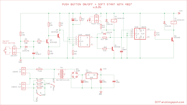
The third variant is using two transistors as input stage instead of inverter with Schmitt trigger:
These three schematics was tested on breadboard with 4027 from different manufacturers and work without problems.
So, how they work? When the circuit is connected to the power, the Reset pin will be shorted through the capacitor to the positive rail and the first J-K flip-flop will stay low until capacitor is charged and all transition processes finish. When the push button is pressed an impulse will be send to the clock input of the J-K flip-flop. It doesn't matter if the impulse is low-high-low or high-low-high. In the first case the J-K flip-flop will toggle at the beginning of the impulse (when push button is pressed) and in the second - will toggle at the end of the impulse (when the push button is released).
When the first J-K flip-flop is switched high the first relay is turned on and the load is connected through the power resistors to the mains thus limiting the inrush current.
The capacitor C7 connected to the Set pin of the second J-K flip-flop start to charge through a resistor until the voltage is high enough to toggle the output to high and turn on the second relay. The second relay shorts the power resistors and the load is connected directly to the mains.
The second push to the button will switch off the first J-K flip-flop and the first relay. The capacitor connected to Reset pin of the second J-K flip-flop will discharge instantaneously through the diode D2 and the second J-K flip-flop will switch off, releasing the second relay.
The delay of the second relay is determined by capacitor C7 and the resistor connected to it. with 10 MOhm and 100nF the delay time is about 0.8 seconds. The same time will be achieved with 1 MOhm resistor and 1uF capacitor. Delay more than 1 second usually is not needed.
Schematics work with power supply from 5 to 15 V. The transformer should be select according to the desired DC voltage. For 5VDC transformer with 7-9VAC will do the job and for 12VDC transformer with 12-15VAC will be perfect. The voltage regulator also must be select accordingly. Of course the relays also must match the DC supply voltage.
Here are the files for the project including Gerber files. The third variant is entirely with through hole elements and one sided board. Other two are two sided boards with mixed TH and SMD elements, but there are only couple of tracks on the top side, which can be replaced with wire bridges and thus the boards can be made one sided.
Download link: SoftStart v.3
This is demonstration of the third variant on a breadboard.


Hello,
ReplyDeleteI would like to try the soft start / on off switch.
I see the pins for 4027 and 40106 at schematic is different from layout.
Please advice me which to follow?
For example pin 16 of 4027 in layout is connected but at schematic not assigned.
Thank you
Some of the power pins on the schematics are connected at the power supply circuit and not at the actual symbol of the IC. It is for the clarity of the schematics.
Delete