
I found that there are numerous versions of the famous Microchip PICkit 2 on the web. Some of them are using the original schematic published by Microchip and some are lite versions - with different parts or simplified schematics. None of them satisfied my requirements. So I got the original schematic, removed the memory chips and the input ICSP connector (which I didn't plan to use anyway) and made a new single sided PCB. I used mostly SMD parts.
I found out that I can get all parts for the original schematic from local stores, and only two - MCP6001U and FDC6420C - I had to order from Farnel. I also decided to replace two Schottky diodes BAT54 and ZHCS1000 with SS14 because of more convenient package.
I programmed the PIC18F2550 microcontroller with my Chinese programmer.
Here is the schematic which I used:

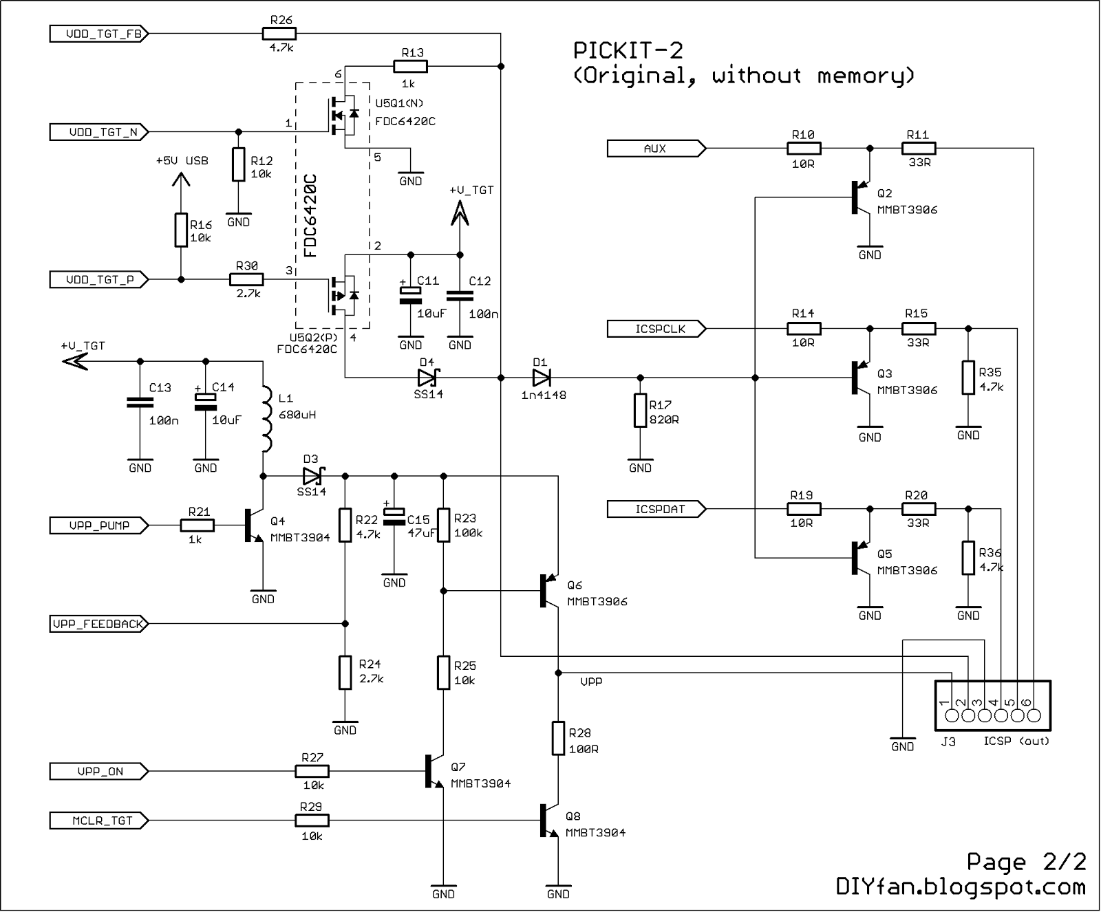
In the end the schematic is not exactly like the original one but it is close enough :)
I used the same notifications of the parts like in the original schematic.
PCB which I made is very satisfying:

It is one sided and has only five jumpers. The size is comparatively small - 83mm x 52mm.
And the final product:


I don't want to brag, but I think I made the best one sided PCB for PICkit 2 programmer :) .
It also works without any hiccups. I tested it with an PIC16F628A which I have at hand. It was recognized in both PICkit 2 software and MPLAB IDE.
Here is the picture of the programmer connected to the breadboard with the PIC16F628A on it.

Connecting cable is made from short piece of LAN cable.
Later I will make a separate board with 40 pin ZIF socket for easier programming of various models of the PIC microcontrollers.
If anyone wants to make their own PICkit 2 here are the files of the project: PICkit 2
Inside are the PCB and the schematic in PDF format, parts list and also the latest version of the firmware for the PIC18F2550 and the user guide from the Microchip site.
Use them on your own responsibility.
Update: 25 June 2013
Here how I made the ZIF socket adaptor:


It is very simple approach - necessary connections are made with wires so care must be taken which pin goes where.
Hi
ReplyDeleteI am a newbie to PICs. I am planning to build myself a PICKit 2 (lite) programmer. I have check various circuits online and want to know what is the difference between the circuits with an op-amp and the one without an op-amp. The circuits without the op-amps are also claimed to be the lite version of PICKit 2. What is the advantage/disadvantage of the op-amp?
I am not sure what the advantage/disadvantage of the opamp is in the circuit. There are different meanings of "lite" in different versions. Some of them use different parts, and others have simplified the schematic. Mine, as explained in the article, is almost identical to the original, except removed memory chips, connector for on board programming of the microprocessor and two Schottky diodes replaced with equivalents.
DeleteThe op-amp permits to adjust/tune precisely the target-Vdd and at least to switch it on or off. Lite versions with permanent Vdd have a big drawback: you cannot use the "Vpp First" procedure that is the only possibility to reprogram a PIC that had been programmed with MCLRE=OFF. In that case it is has you have an OTP...
Deletehi
ReplyDeletewhat toner transfer method you used?? (the pcb is too neat)
Hi.
DeleteI use phototransfer method with photoresist POSITIV 20
It's a bit complicated and slow, but the results are good indeed :)
I see you did this in EAGLE Version 6.3.0, and wonted to ask if you could share the Eagle files.
ReplyDeleteDoes this support 3.3V MCU? I dont see any jumbers so i assume it doesnt. Nice work by the way.
ReplyDeleteYes, it support. There isn't such jumper in the original PICKIT-2 too. The desired voltage is selected automatically or manually by software used for programing the microcontroller.
DeleteThanks a lot for replying mate. I appreciate it. Cheers.
Deleteby the way....Is there any way you might have a circuit for some very simple parallel programmer for that 18f2550 ? :P (chicken egg problem...)
ReplyDeleteThe best solution for you is to find someone locally - friend, or colleague, who own a programmer and who can program it for you. But if you can't find such person, then here a good collection with simple schematics for programming PICs via parallel, serial or USB ports: http://picpgm.picprojects.net/hardware.html#LVP_PROGRAMMER
DeleteThank you very much. I am going to build one.
ReplyDeletehow did you make the PCB nice and clean ,,please share on may email...spyruspy28@gmail.com
ReplyDeleteHi nice work there,
ReplyDeletecan i replace "MMBT390" with 547 transistors ?
and doe 1mH work if repalced with 680uH ?
Hi,how can I buy PCB and with all materials.Thanks.
ReplyDeleteHi,
DeleteIt is really not worthed - you can buy from ebay Pickit2 for $8-$9 or Pickit3 for $11-$12. I can collect all the parts and make a PCB, but the price will be at least $30-$40.