
It has adjustable output voltage from 0 to 30V and adjustable max output current from few miliamperes to 3 amperes.
As it turns out there are serious flaws in it, but in the forum in that site it was thoroughly discussed and the member audioguru proposed an improved schematic, in which all flaws were addressed. I used his schematic to build my new power supply.

 |
| This small heatsink is only for test purposes and in the final product there will be a much bigger heatsink and maybe also a fan. |
After I built it and did some testing I made two changes: first, I added 24V zener diode + resistor to stabilize supply voltage on IC1. This is especially important because when there is high load and supply voltage drops by few volts reference voltage on pin 6 also changes significantly.
Second, I removed 10k trimmer resistor RV1 - there isn't any need for it.
Here is the final schematic:

The two trimmers are for adjusting the max output current and the max output voltage.
And some shots of the second PCB and assembled board:


My plans are to make 2 pieces in two separate chassis and when I need dual voltage supply or voltage higher than 30V I will use both of them.
There will be digital panel meters on the front of the chassis which I already ordered from eBay.
Update (13.03.2012) :
Finally, over a month after ordering, the two transformers are ready. They are capable of delivering 30V/4A.
The panel meters also arrived from Hong Kong.

As you can see, I have replaced 0.47 ohm/10W resistor with two 0.68ohm/10W resistors in parallel, because the former generated too much heat.
The front panel is also ready, later will post a picture. What is left to do is to make a little board with a fan controller.
Here is the link for downloading archive with project files in PDF format: LabPS.rar
The first one of the two PS is ready!
Here is puny board of the fan controller:


And there is power supply itself:

Here is the schematic of the fan controller:
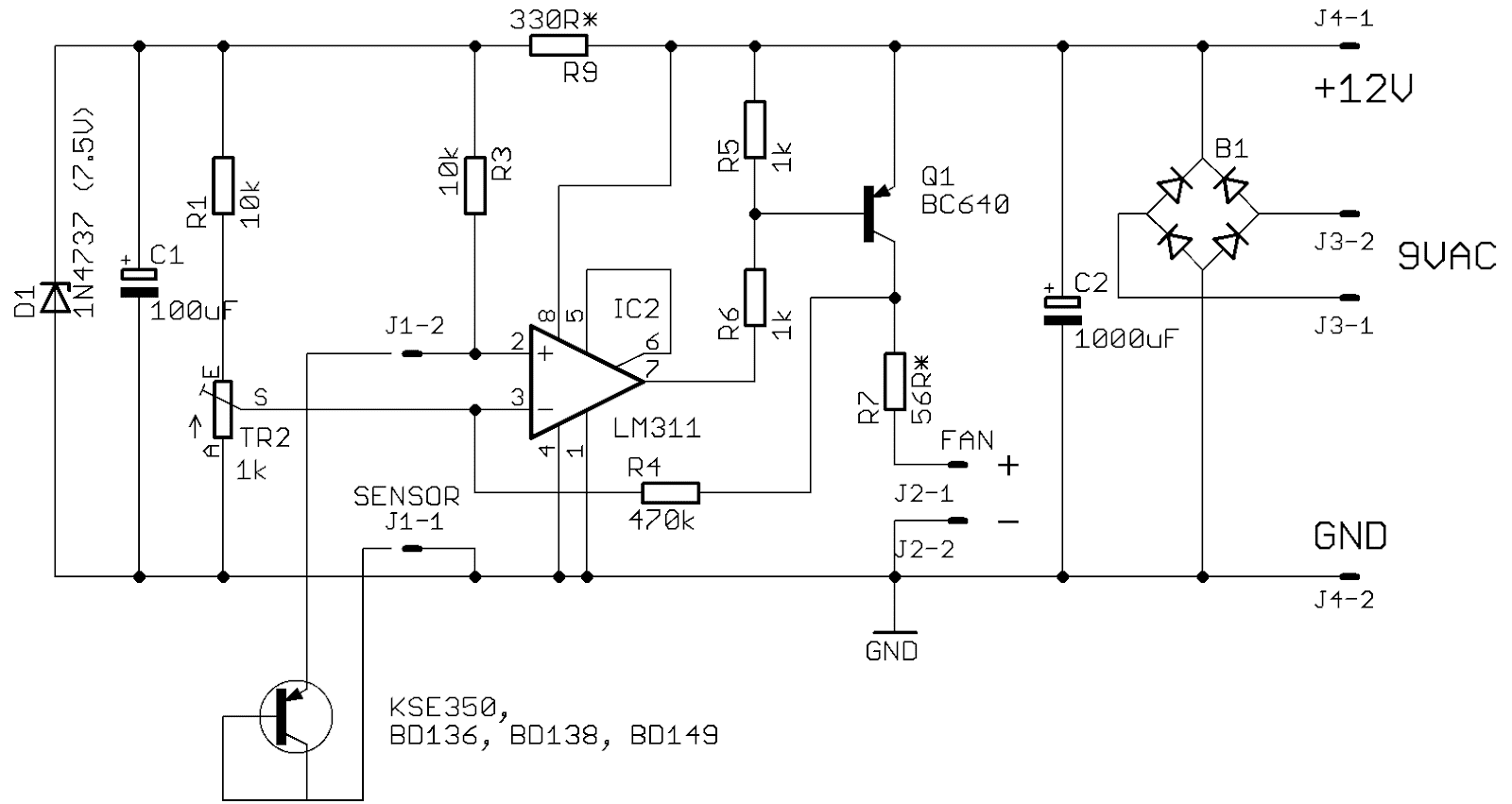
The schematic may be supplied with AC or DC voltage but not both simultaneously. If the supply voltage is DC, then B1, C2 and J3 may be omitted. With different R7 value we can control the speed of the fan. Adjusting switch-on temperature is made with TR2.
And here is the link for downloading: FanControl.rar
The PCB is different from that shown on picture above, because I made some improvements and rearrangements.
Use it on your responsibility.
P. S. There is even smaller version here: FanControl2
Update: 17.05.2012
The second unit is almost ready. Here one shot from inside:

The fan is secured to the bottom with double sided adhesive tape.
Update: 20.05.2012
It's done! Dual adjustable laboratory power supply :)

Update: December 29, 2015
I was asked couple of times how to connect center tapped transformer to the power supply. It can be done according to the schematic bellow. The bridge rectifier is replaced with two diodes. The negative voltage come from one of the windings. It is rectified by D3 and smoothed with C3. D1 and D2 must with high current rating - at least 5A (diodes in the schematic bellow are just for illustration). C3 must be with 50V or 63V rating. R1 and R2 must be 2W power resistors. There can be added a capacitor (100uF) between -V and GND for extra smoothing the negative voltage. If the negative voltage is bellow 1.3V, the value of R1 and R2 can be decreased a little. Bear in mind that I haven't tried this schematic, just simulated it, so be careful.

Hi. How can I get this circuit board?
ReplyDeleteI will put a link for downloading within a few days.
ReplyDeleteХристо, это будет замечательно! Буду ждать.
ReplyDeleteBoard very nice. Thank you. And for you, if need: http://www.elektroda.pl/rtvforum/topic975213.html. Power, current, thermostat and fan, current limit.
ReplyDeleteIt's worked.
Good job. Small and cute. We look forward to the scheme and the board fan control?
ReplyDeleteIt does not work. Do not set a zero output and adjustable current limit. Details are intact, the board checked twice.
ReplyDeleteDouble check all elements. What IC you use? I tried with TL081 and OP07 and current limit didn't work well.
ReplyDeleteAlso you may try without Q2. If it work without Q2, you may try to put it back and increase the value of R13.
What is the voltage of the transformer?
Also check the correct connection of power transistor.
I'm sorry. Everything is working. Just two tracks were combined. When cleaned up - the problem disappeared. Christo, thank you. Very good board. Later, if you like - I can show pictures of my power supply. And the issue. Christo, the board can do for the other diodes? For example - KBU10M. I could not find Bridge Rectifier as yours.
ReplyDeleteI am glad that everything is working. The KBU10M would be just fine, I think, with proper cooling.
ReplyDeleteIt would be interesting to see pictures of your work.
I think you can make changes to the board to set KBU10M. I have a board just because of the PDF and I can not make changes.
ReplyDeleteThe rectifier I use i very common and cheap. You may also use diodes like these http://www.rectron.com/data_sheets/10a05-10a10.pdf to make a discrete rectifier, and arrange them in such way to fit the holes in board.
DeleteHey, can you upload a full parts list?, i'm a little confused on what exactly B2 is.
ReplyDeleteB2 is 35Ampere bridge rectifier.
ReplyDeleteHere the link to partlist: http://dl.dropbox.com/u/68795389/LabPS_partlist.txt
Thanks a lot, that's really helpful!
DeleteOne more question, when i looked on ebay for the current and volt meters i found that the digital voltmeters were mostly rated at DC 4.2 V – 30 V, that would mean it fails to work below 4.2 volts and the ammeters were DC 7V – 30V. Now that's not much of a problem because i can always hookup a multimeter when its below that range. I was just wondering if you had any problems with the high and lower ranges.
There are two types of voltmeters - first type use input voltage for supplying itself. They cannot measure lower than their minimum supply voltage.
DeleteThe other type use separate supply voltage and can measure down to zero volts.
I bought mine from here: http://www.ebay.co.uk/itm/180670991833?ssPageName=STRK:MEWNX:IT&_trksid=p3984.m1439.l2649
Ah yes that's the one I was looking for. For some reason it wasn't coming up in my eBay search.
DeleteAlso is this transformer fine - Cat. MT-2086 15+15 Volts 0.666 amps 1.333 amps. I'm thinking it won't be because the amperes are way too low even though it outputs 30V if you combine the two 15V taps.
http://www.jaycar.com.au/productView.asp?ID=MT2086&keywords=toroidal&form=KEYWORD
Is this one better?, Cat. MT-2113 18+18 Volts 4.44 amps 8.88 amps.(same page as above but 160VA). That has two 18v taps when combines you get 36V which is a higher and the amps are higher also. The problem I'm having is finding one that steps 240V down to 30V. Most of the one's on eBay run 110V.
I think neither of them is suitable. The first have too low amperage, it will provide max 0.5A at output of power supply. The second transformer have too high voltage, after rectification there will be approximately 50VDC, which is too much to be handled by this schematic.
DeleteMaybe this one will be more suitable :
Deletehttp://www.jaycar.com.au/productView.asp?ID=MT2114&form=CAT2&SUBCATID=1002#12
The two secondary windings connected in parallel will provide 25VAC / 6.4A.
The rectified voltage will be 34-35VDC, which I think will be sufficient.
So if I use this transformer with the circuit shown if will work with no problems and give me a 30 Volt DC / 6 Amp Power Supply?
Delete160VA TOROIDS
- Size 110 O/D x 50 I/D x 40(H)mm
Secondary Series Secondary Parallel
Cat. MT-2114 25+25 Volts 3.2 amps 6.4 amps
Thanks for your time and have a great day!
Rick
[URL=http://radikal.ru/F/s019.radikal.ru/i607/1204/65/cd226b81c0c5.jpg.html][IMG]http://s019.radikal.ru/i607/1204/65/cd226b81c0c5t.jpg[/IMG][/URL]
ReplyDelete[URL=http://radikal.ru/F/s49.radikal.ru/i125/1204/7d/91d498314307.jpg.html][IMG]http://s49.radikal.ru/i125/1204/7d/91d498314307t.jpg[/IMG][/URL]
My device. Христо, thank you for board.
Thanks for all your help. I'll use that one.
ReplyDeleteI noticed on your final photo you have a third potentiometer. Is that for fine tuning?
Yes, it is 1kOhm linear potentiometer for fine tuning of output voltage. Connected as suggested by audioguru in the forum - in series with the other potentiometer.
DeleteHi, do you have the project/design files; the files I can open with proteus? Are the PCB files the ones in the compressed files? They look a little bit different than the ones you used on yours.
ReplyDeleteThanks a lot.
I don't use Proteus, sorry. The PDF files in the archive are the latest versions. I modified/optimized PCB, and that's why it is different from these in the pictures.
DeleteOh okay, thanks!
DeleteHi there, I finally did find this thread and is exactly what I was looking to generate up to 24V lab supply. How ever, Is there possible that you generate same circuit for 0to -24V supply? Some op-amps and such need negative supply and it would be nice to build single power supply that has both positive and negative supplies.
ReplyDeleteYou may build two pieces like I did, and put them in one chassis. Also you may use one transformer with two separate secondary windings. One of the outputs would be 0..24V and the other - 0..-24V
DeleteDo you have schematics and bord files for EAGLE or similar software?
ReplyDeleteI can provide you with schematics in EAGLE, I can also provide board layout, however mine differs from the original layout in certain connectors and other parts I am using and I have not routed any traces. If you cannot get the appropriate files from the author, I can provide you mine.
DeletezYour post includes great tips and you managed to keep it simple and understandable. Thanks for sharing.circuit board
ReplyDeleteI think that the author will not mind if you put your version of the board. I too will be glad to see another option.
ReplyDeleteHello did anyone tried using the TLE2141 as a substitute to MC34071?
ReplyDeleteThanks.
TLE2141 is suitable for this schematic, I think. When I chose which IC to use, I selected MC34071 because it was cheaper.
DeleteThanks for the reply.
Deletewe need also its pcb measurements,.. was the pcb layout in the PDF format was in the actual size?? thanks,,
ReplyDeleteYes, the PCB layout is in actual size, so the PDF file must be printed with "100%" or "Actual size" options selected.
Deletethank you for fast reply.. :)
DeleteWhat other component/s that i can replace to MC34071? Beside TLE2141?
ReplyDeleteI don't know, sorry.
Deletehttp://www.electronics-lab.com/forum/index.php?topic=19066.1330 - the last two postings are about the same question.
thank you.
Deletehai...we plan to build your circuit because we failed at the first....my questions are..
ReplyDelete..where i put my ammeter?
..can i use 24v 6amp transformer?
..is the voltage adjust from 0 to 30v?
..is there any replacement of the i.c mc34071 beside tle2141?
..is the over current works well? in what way?
..do you have any write up in this circuit or documentation how it works?
..do you have bigger trace in your layout because we manually layout and the trace of the circuit...pls..
..we are using 1n5402 3amp rectifier...is that ok?
thank you..
1. You must put ammeter in series with PS. Here a simple schematic of the connection of the ammeter and voltmeter to the power supply: http://electronics-diy.com/schematics/1179/digital-volt-ampere-meter-power-supply.gif
Delete2. Yes, you can, but the max output voltage will be lower than 30V - maybe 26-27V.
3. I tried with TL071 and OP07, but the current control didn't work well.
4. Max current is adjusted with one of the potentiometers and if the load is higher, then schematic work as constant current source, maintaining adjusted level of the current.
5. In the beginning of the article there is a link to original project, where you can find more information. The project is discussed in details also here: http://www.electronics-lab.com/forum/index.php?topic=19066.0 and here: http://www.electronics-lab.com/forum/index.php?topic=7317.0
6. In the above links you can find other PCBs which may suit your better.
7. 1N5402 is OK, I think.
my teacher said that the ammeter panel display,put on the 10w resistor parallel with it. they call this sensing resistor..is that wrong?
ReplyDelete..in the first circuit that we made, if we put a load it will drop down up to 2volts, my load is power led which the supply is 12volts.
The connecting depends of what type of ammeter you use. Most analog ammeters have installed shunt resistor on them, so there is no need do connect additional shunt resistor.
DeleteIf ammeter is for low current, for example 1mA, then you must calculate proper value and power rating for shunt resistor. BTW, 2V drop voltage is too high.
I think, the best solution is to get ready for use ammeter - 3A or 5A.
is your circuit have a ,short circuit protection?
ReplyDeleteAs I said, when there is higher load (and short circuit is just that) the schematic start to work like a constant curent source and limit current to previously adjusted max value.
Deletei have a problem about my voltage adjust(potentiometer), the problem is that the voltage is not balance and not linear, my minimum voltage is 0.7v and max with 32v, but if i adjust the potentiometer 1/2 the voltage is only 1.3v, in 3/4 of my potentiometer i can adjust the voltage properly start by 3v-32v but i really wonder why the voltage is gather in the 3/4 of my potentiometer???? i use 10k pot, i already replace it 3x,, but the same thing happened., i also replaced it with 1k value, but the max voltage lower, only 7.4v,,.. can you help me sir???thank you!!
ReplyDeleteMaybe your potentiometer is logarithmic? I use 10k linear potentiometer, as is specified in original schematic and adjustment is linear. When potentiometer is turned halfway the voltage is roughly 15V.
Deletehow much that linear pot?
ReplyDeleteIt's nothing special - I got mine for 0.50 USD :)
Deletevery nice presentation, and the board you have posted is very functional. I finaly etched the one picmaster suggest, because I found yours later, but I have a couple of friends envy with my power supply :)
ReplyDeleteI have a question though. from where do you take the DC voltage needed for the fan controler? My project also needs a fan but putting a second transformer seems a little bit too much for me :)
My transformers are custom made and have second secondary winding which supply the fan controller and the ammeter. The voltmeter gets its supply voltage from main board (there is not a dedicated connector though, cables are soldered to the bottom).
DeleteYou may use 24V fan and get the supply voltage from the main board after rectifier and big capacitor. There must be a resistor in series with the fan, which value and power rating have to be calculated according to the fan current. For example if the rectified voltage is 40V and the fan is 24V/0.1A then the voltage drop on the resistor will be 40-24 = 16V. The value of the resistor will be 16V/0.1A = 160 Ohm. The power dissipation will be 16V*0.1A = 1.6W and the power rating must be 3W or greater.
thanks..can i asked you? did you try to assemble a power amplifier?
ReplyDeleteDidn't you browse my blog? There is couple of solid state power amplifiers, numbers of Gainclones and two headphone amplifiers - all of them assembled by me.
DeleteSo, the short answer is yes :)
I have downloaded the fancontrol files but they are not scaled 1:1. What scale must I use to produce the pcb correctly?
ReplyDeleteCan I use the BD139 for the temperature sensor? Where and how should the temperature sensor be mounted?
ReplyDeleteAbout first question - yes, they ARE scaled 1:1, they are just very small :)
DeleteTemperature sensor must be mounted to the heatsink of controlled devise, preferably close to the power transistor.
PNP transistor like BD138 or BD140 is more convenient because the metal part of the body (collector) is connected to the ground and if the heatsink of controlled devise is also connected to the ground, there will be no need of electrical insulation between the transistor and the heatsink.
If you have to use NPN transistor like BD139, it must be connected in reverse manner - the base and the collector to the pin 2 of the LM311 and emitter to the ground. And it must be mounted with some mica or silicone insulator to the heatsink
Thank you for the prompt reply. Looking at the fancontrol pcb layout I now see that it is scaled 1:1. I will need to redesign since I have purchased the socket mount LM311, not the surface mount LM311.
DeleteI am using 3 x TIP3055 SOP93 packaging for 5A version. They are isolated from the heatsinks, so I will try the BD139 because I have some.
New issue - I tried to follow the 100s of pages of commentary on Electronics Lab, and in the discussion about measuring current, Audioguru made a good case for measuring the voltage across the output current sensing resistor (in some circuits R7). With this in mind I ordered 2 x 0-99V digital voltmeter 3 digit displays - one for volts and one for amps, but I then realised that the volt drop across R7 varies from 0 to 1V. Is there a practical way to use the 0-99V for current?
Regards
I doubt. Usually these voltmeters are with some microcontroller with 200mV input range and a voltage divider to allow measuring higher voltage range. Without the schematic it will be very difficult to find and replace the resistors in the voltage divider. And usually these resistor are tiny SMDs...
DeleteMy advise is - keep second voltmeter for another project and buy a proper ammeter.
Nearly complete and all looks good.
DeleteI am using your fan circuit and I use 9Vac transformer which gives me regulated 12Vdc with no load. When I connect the 12V fan the voltage out drops to 9.5Vdc. I assume the volt drop is across R9. Can I use another value and what is the calculation?
Yes of course, you may completely remove that resistor and put an wire jumper instead. Its all depend how loud is your fan at full speed. The exact value of the R9 is determined with testing.
DeleteJust to confirm - I understand I can short circuit R7 since this controls fan speed. But I refer to R9. This cannot be short-circuited from my understanding of the circuit. Why would the voltage across the fan drop from 12V to 9.5V when fan connected?
DeleteSorry, I was talking about R7, but wrote R9.
DeleteR9 has nothing to do with relay voltage. Together with zener D1 they form stable voltage for the voltage dividers R1 - TR2 and R3 - sensor. R9 is adjusting according the voltage drop across R9 and Iz of the zener. For example, if we have 12V supply voltage and 7.5V zener with Iz = 10mA then voltage drop is 12 - 7.5 = 4.5V. R9 then will be 4.5/0.01 = 450 Ohm.
Voltage drop is because of R7.
I have built the 30V 5A version and at full power it needs a lot of cooling. Originally I had a 9V 100mA dedicated transformer and used your cooling fan circuit with no changes. But there was not enough cooling since the fan is rated 130mA 12V.
DeleteSo I replaced with a 12V 500mA transformer and all worked well for a few weeks. Now the fan has stopped turning on - the fan itself is fine, I checked. The temperature sensing is fine, checked.
What else should I check, and what circuit design changes do you recommend for the higher voltage and power?
Hello, is really nice de ps, I have a simple question, to set (limit) the current?, can I put an amperimeter without load?, I know it is like a short circuit, but with the ps I have in the uni is like that. Sorry for my english. Regards
ReplyDeleteYes, this is the way that I use to adjust the current limit. Because I have installed ammeter, I just make a short circuit to the output terminals and adjust the current to the desired level. This procedure must be done very quickly or else there is danger of damage.
Deleteok!, thanks very much!, I will make the ps, in a few weeks. Regards
ReplyDeleteHello,
ReplyDeletecan you please tell me the specification of the transformer you used in this project.
As I can see, you have two secondary winding, first can deliver 30VAC at 4Amps, what about second?
Regards
The second secondary winding is 8VAC/1A and is used to power supply the fan control module and the ammeter. Additional small transformer may be used instead for this purpose.
DeleteOk,thank you very much for the answer!
ReplyDeleteRegards
Hi, can i use LM741 instead of MC34071 ?
ReplyDeleteI can't fiind any MC34071 in my area.
Thanks.
I am not sure... Maybe you should ask in this forum: http://www.electronics-lab.com/forum/index.php?topic=19066.0
DeleteI used an 741 and it works fine.
DeleteIs this circuit works LM741 in perfect as which as mc34071
Deletehi, good day........do you have a schematic diagram of up and down counter from 0-60? if you have,can i ask the diagram...please..please....don't say no....
ReplyDeleteSorry, I don't have such schematic. You have to search for some BCD counters.
DeleteHere two links that may be useful to you:
http://www.youtube.com/watch?v=TAXS9NhBibo
http://www.doctronics.co.uk/4511.htm
Hello, friend. I have a question, may sound stupid, but I'm really in doubt. What does the fan controller? Only provides voltage and current to the fan? Thank you!
ReplyDeleteFan controller keeps track the temperature and switch on the fan when heatsink gets too hot. When heatsink is cooled down then the controller switch the fan off.
Deletethank you...muahhhhh
ReplyDeleteHI. I've noticed that your pdf of the layout is not true black and white. The "black" parts look a bit grey compared to real black. This leads to problems with my toner-transfer setup because the printer dos not use enough black when trying to do a grey-scale.
ReplyDeleteCould you be so kind and post another pdf with the layout in true B&W?
Kind regards Troels
It is not grey. When exported from Eagle to PDF, black areas are composed of tiny parallel black lines . When displayed on the monitor sometimes it looks like grey, but if you zoom it enough you will see that it's black.
DeleteThis comment has been removed by the author.
ReplyDeletehttp://www.youtube.com/watch?v=r490iPXKo7U
ReplyDeleteThanks alot. i have decided on building this as a bnch top PSU
ReplyDeletebut i want to power it from a 33V Swichmode DC supply..
i understand the "lower part" of the circuit
R2, C2, D2,D3 D5 C3...etc is there to produce the negative voltage rail for the opamps
i want to substitute this. can i just use a -12v supply or what?
i have +12 and -12 available for the opamps ?
Thanks Alot
You may use 33VDC for the circuit but -12V is too much for the negative rail. You may reduce it with resistor and two diodes (as it is on the schematic) or resistor and zener or even a 3-pin regulator for -3.3V
DeleteYou may not supply the opamps in schematic with +12V and -12V, because the maximum output voltage will be around 10-11V
This comment has been removed by the author.
ReplyDeleteso i suppose just populate R3 D2,D3
ReplyDeleteand hook -12 or even -5 volt there. ?
let the diodes regulate it. so the circuit
functionality is unaffected ?
/Kyndal
Yes, that will work. If you connect -12V then R3 must be increased to 470 ohms.
DeleteYou may also look at this article: http://diyfan.blogspot.com/2013/03/adjustable-lab-power-supply-take-two.html
Hello!
ReplyDeleteI liked this PSU! It is simple enough for me to build and you also provide the files. So if I make the PCB it is going to make my life extra easy!
The problem is that I would like to make it bigger current capable. Do you think I could put a second 2N3055 in parallel (with small power resistors of course) and make it 5A capable? I have a 150VA transformer so it would be a pitty not to use the extra power.
What do you think? Would it work like this?
If you go for 5A version, then R7 must be 0.27Ohm and the heatsink must be HUGE and there must be active cooling (fan). The C1 capacitor is recommendable to be bigger - 12000uF or 15000uF.
DeleteI suggest also to look at my new version of this schematic: http://diyfan.blogspot.com/2013/03/adjustable-lab-power-supply-take-two.html
And one last advice - the output transistor(s) must be with highest possible current gain (hfe).At 5A output current if current gain is 10 then base current will be 0.5A and driver transistor (BD139) will get very hot.
DeleteHi you have in pdf file the top elements of pcb power supply and fun control without tracks solders only side of components design? Thanks
ReplyDeleteSorry, I have not this kind of PDF, and because I made some further changes of the PCB I can not make new PDF - it will be different.
Deletein your circuit diagram their is 2 pot resistor by in your final supply their is 3 pot resistor in front display
ReplyDeleteThe third potentiometer is for the fine adjustment of the voltage. It's a 1k linear potentiometer connected in series with the 10k potentiometer P1. The schematic will work without it just fine.
Deletecan use 30v 5amp tranformer
ReplyDeleteand this 5 amp transformer give output current 0-5 its posible
Yes, you can use that transformer, but the output current will be max 4A. You may consider connecting two power transistors in parallel with emitter resistors. There is a lot information about that in the forum: http://www.electronics-lab.com/forum/index.php?topic=19066.0
DeleteI am going through your Version 2 and version 3...which is the best among them.
ReplyDeleteIf you mean this project: http://diyfan.blogspot.com/2013/03/adjustable-lab-power-supply-take-two.html then I recommend ver. 3 - it is simpler and with less parts.
DeleteI believe it could use an LM358 to replace 2 opamp and as a reference voltage an 78l12 or other. The use of LM358 eliminates the needs os the -5.6V to 0V output voltage. I have not tested yet with this changes, but I believe it works. What do you think?
DeleteDear sir....if i am having a low input mains @ maximum load which version do you suggest me.
ReplyDeleteI don't understand your question here. What do you mean with "low input mains @ maximum load"?
DeleteDEAR SIR..here we have a mains supply variation from 200-240 volts during peak load hour and off load.
ReplyDeletethe DC o/p supply need to be stable in all ranges of input mains .when i load the power supply in this variable voltage condition (mains ) what is the load regulation Vs line regulation.
I think all three designs will be quite stable, if input voltage is 5-6V higher than output.
DeleteAlso cables connecting output to terminals must be short and thick to minimize voltage drop on them.
dear sir,
ReplyDeletewe assembled the 3rd schematic. But the output voltage is only adjustable from 0- 10.6 volts without load.
we have checked all possible errors ,but none.Pl suggest me what is wrong or suggest me where should i check.
The AC input is 30 Volts /2 amps .
And why comment here, the 3rd schematic is in another post? Anyway.
DeleteIs the current limit set to "min" when you test the output voltage?
Check these voltages:
1. Across C1 there must be around 40-42VDC.
2. Between the ground and the output of LM317 (IC3) there must be 33VDC
3. Between the ground and the output of LM337 (IC4) there must be -3VDC
4. Across the two zeners Z2 and Z3 there must be 9.5V
5. Between the input of IC1B (pin 5) and the negative output voltage must vary from 0 to 9.5V as you turn potentiometer P1.
6. between the output of IC1B (pin 7) and the negative output voltage must vary from 0 to 27-32V (upper limit is adjusted with trimmer P4).
7. Measure the output voltage of IC1A (pin 1) at 0V and at 10.6V output.
Check also is anything heating up.
dear sir,
ReplyDeleteThank you so much for your support and response.We made it all right. There a value change of R12 ,which was corrected.I will load the circuit and reply tomorrow. Thank you again.
is it possible to substitute by TL081CN ?
ReplyDeleteTL081CN analog?
No, this opamp is not suitable for the schematic. Check the other version in my blog: http://diyfan.blogspot.com/2013/03/adjustable-lab-power-supply-take-two.html
Deleteпо даташиту подходят
ReplyDeleteif to believe datasheet that they are analogues
ReplyDeleteAbsolute maximum supply voltage of TL081 is 36V, but IC2 may receive up to 40-42V (depending of the voltage of the transformer), which may destroy the chip.
DeleteAlso there is that effect "phase inversion": when the input voltage of IC goes close to the negative supply voltage the output voltage goes high. More about that you can read here: http://www.electronics-lab.com/forum/index.php?topic=19066.0 and here: http://www.electronics-lab.com/forum/index.php?topic=7317.0
hi, I think your Fan control file got hacked, as when I download, it try to download an Fancontrol.exe, which I though is odd and then my anti-virus kick in and zap the file. Could you post the file again ?
ReplyDeleteNo, it's not hacked, I just tested it. You must have account in 4shared.com for downloading the archive. If you got strange links, then maybe your computer have some malicious software that replace valid links in web pages.
DeleteMC33071pbx ?
ReplyDeleteThis opamp probably will work fine with the schematic.
DeleteI don't know what 'pbx' suffix mean though.
during connecting of motor-car lamp 20W 12v a transistor burns BD139
ReplyDeleteSo?
DeleteReplace it and make sure it's cooled with appropriate heatsink.
кт805 put
ReplyDeleteall became ок
Getting an old broken power source to work can be hard money washington. But it's doable if you know how to do it.
ReplyDeleteHI i build this 0V to 30V 3A circuit and i connected a 15v 0v 15v 3A transformer to it and all works well but the transformer gets extremely hot when left on for 2 hours or more with no load connected to the output of the power supply circuit why ?
ReplyDeleteDisconnect the PS and run only the transformer without load - if it gets hot, then the problem is in it. It can be shorted winds or loose core laminations.
DeleteThe PS circuit consume max 20-30 mA without load so I don't think the cause is in the schematic itself. You can also remove the fuse and measure the current with an ampermeter, connected across the fuseholder.
Can anyone tell me if there is any problem / how to use this Amp / Volt meter display with this power supply? It is at the following link:
ReplyDeletehttp://www.aliexpress.com/snapshot/314998794.html
See this page: http://www.ebay.com/itm/New-Red-LED-DC-0-100V-10A-Dual-Digital-Voltmeter-Ammeter-Panel-Amp-Volt-Gauge-/261273650917?pt=LH_DefaultDomain_0&hash=item3cd51f86e5
DeleteI think it's the same meter and there are some schematics about how to connect the meter.
See this supply before going through the trouble and expence of making 2 of these:
ReplyDeletehttp://www.automationtechnologiesinc.com/products-page/mastech-power-supply/mastech-hy3003f-3 Can't beat the price.
Yeah, it's easier and maybe even cheaper, but where is DIY, where is fun?
ReplyDeleteFrom this pic:
ReplyDeletehttp://1.bp.blogspot.com/-mDEuvnxlus0/T7TSjC1R7nI/AAAAAAAAATs/Djy43S2SUSE/s1600/LabPS9.JPG
Where is your ammemeter getting power from?
What is the use of 'PAD1' on the board?
I'm sorry...I'm pretty new to electronics.
The ammeter is powered from fan controller board, which in turn is powered from another 9VAC winding of the transformer. This way the ammeter is independent and can be connected anywhere, in my case it's connected to the positive side of the output.
DeleteThe PAD1 is present in next versions of the power supply and if you read the whole article there is explanation. It's used for powering the digital voltmeter. As the voltmeter require 6 - 27V supply voltage, I reduce the input voltage (over 40VDC) with a zener to acceptable level.
In this version the positive supply input of the voltmeter is connected via zener which is soldered directly to the wire, and the wire is soldered to the cathode pin of D1. Not very pretty but do the job :)
I made the above connection, but I can not regulate the flow.
ReplyDeleteCan you help me?
Did you mean that you made the power supply and can't regulate the current limit?
DeleteIn order to help you I need more information:
1. Did the voltage regulation work?
2. How did you test the current regulation?
3. What OpAmps you use in the circuit?
4. What is the rectified voltage (measured across C1) ?
5. What is the negative voltage (measured across D2 and D3) ?
6. Are all the elements exactly as in the schematic or not?
1. ok, but if the current adjustment knob tension control actuator will have no.
Delete2. ammeter is on R7.
3. im used OpAmps TL071.
4. C1 voltage 19V( I transformer 15V).
5. I dont know now. I know evening.
6. IC1,2,3 except exatly as in the schematic
Thanks
BTW, which of the two schematics do you make?
DeleteThere are two problems:
1) the TL071 is not suitable for this schematic because negative voltage rail is too low and
2) supply voltage is too low.
Here are the changes you must make in order to make working power supply.
1. Remove zener D1 and replace it with piece of wire.
2. Replace D2 and D3 with zener for 5.1V or 5.6V, for example BZX55C5V1, BZX55C5V6. Don't forget to solder it with cathode to the ground. Measure the negative voltage across C3 and replace R3 with suitable value.
3. Replace R22 with 2k2 resistor.
4. Replace D4 with 15V zener (BZX85C15 or 1N4744) and R10 with 180R resistor.
5. You can replace R4 with 220R, R6 with 1k2 and R5 with 5k6 in order to reduce the reference voltage to 6.8V
Do all these steps and maybe the power supply will work.
I make schematic in labps.rar
ReplyDeleteGND-D3 catode 4.5V
hi Христо, I am starting hobbyist.. and enjoyed your article and would like to make your adj power supply. I hope you do NOT mind I am asking but do you have the PCB print out. Thanks Cees
ReplyDeleteThe link is in the article.
DeleteHI for the fan controller R4 470K is there another value that I can use because i can find it and for R7 i have 2 0.47 ohms 10w can I use then thank you
ReplyDeleteR4 sets the hysteresis of the schematic i.e. difference between temperatures of switching on and off. You can replace it with 560k or 680k
DeleteFor R7 you only need only one of these 0.47 ohm resistors. The value of two in parallel (0.23) will be too low I think.
Thanks for your quick answer and for sharing your knowledge and experience is very very appreciate
ReplyDeleteHi, i made your's power supply and i wonder if i can use TL071 instead MC34071.
ReplyDeleteThank u again.
There is very high probability that it wouldn't work.
DeleteFirst, if your transformer have AC voltage higher than 26V, IC2 will have supply voltage higher than 36V, which is absolute maximum according to the datasheet.
Second, TL071 needs higher negative voltage to work correctly. There is this effect called "Phase inversion" - if the the positive input signal goes near to the negative supply voltage, the output will suddenly go as high as possible.
Of course, you can solder IC sockets and try if it works with TL071 - they are so cheap, so even if they burn it will be no big lost :)
If you cannot find the recommended IC's then you may consider my version 3 in the other article. It can work with TL072 or TL082 opamps.
Thank u for your reply, I have tested it with TL 071 unfortunately it is not worked, first i wont to test that version of power supply and then i will make your 3 version, Thank anyway, I have order the MC34071 op amp.
DeleteHi, thank you for the good schematic!
DeleteI repeated it, and all works as well but I have three problems:
1. Strong heat R1 (2k2/2W) and R2(82R/2W) up to 60C-70C even without load. It is good?
2. Then decreases resistance on P1 less approximately than 600 Om, output voltage going to jump on 1.5V to 30V (if on P1 is 0 Om). Then i increses resistance on P1 (after 600 Om) output voltage increses linearly to 24V. What is wrong?
3. Output voltage not reduced less than 1.4V
The only thing I replaced is with BZX85C10 to BZX85C11 (then it was not for sale).
My transformer is 27V / 1.5A
Thanks in advance for your reply!
Igor.
Hi,
Delete1. It is normal for R1 and R2 to heat - this have nothing to do with the load. If this bother you, you can try to fit larger resistors. For R1 also you can replace it with larger value - 3.3k or 3.9k. The purpose of this resistor is to discharge C1 when the power is switched off so it's value is not that important.
2. What op amp do you use? This sounds like "Phase inversion":
http://www.electro-tech-online.com/attachments/opamp-phase-inversion-png.60318/
3. How much is the negative rail voltage? This is between GND and pin 4 of IC3. There must be -1.3...-1.4V.
Probably the 2. and 3. problems are caused by op amp you use. In most cases if you replace the recommended MC34071 or TLE2141 with TL071, TL081 or something similar, then you can expect such behavior.
Thank you for reply!
ReplyDelete1. I understood for the R1 and R2.
2. As an op amp, I used TL081CP, may be an error in this? Yes, "my effect" is very similar to "Phase inversion". Voltage between GND and pin 4 of IC3 is -1.59V. It is normal?
Thank`s,
Igor.
The negative voltage is OK.
DeleteThe problem obviously is the op amp - TL081 is not good for this schematic. If you cannot find MC34071 or TLE2141, you can try with NE5534.
Another possible solution is to replace two diodes D2 and D3 with one zener for 3.3V (of course connected backwards). This can solve the "Phase inversion" problem, but the IC2 will have a little higher supply voltage and so there will be higher risk of failure.
Hello!
ReplyDeleteI found very simple scheme of the fan temperature control. I tested it and all OK!
May be useful for you http://www.radiolocman.com/shem/schematics.html?di=47949
It is interesting schematic of course, maybe I will test it.
DeleteThanks for the link.
To avoid work near the maximum voltage rates of the opamps, elektor publishes an version of a power supply where the control uses 2 diferent ac voltages: one 12-0-12V 300 mA to control the circuit controller of the voltage and the current limiting; and another AC voltage, evem 50V 10A to works as the "main" power suply. It was published in June 1986 on the portuguese edition of elektor magazine.
ReplyDeleteThe schematic can be found here http://www.eevblog.com/forum/beginners/help-me-choose-an-lm723-based-psu-design/
DeleteI believe it could use an LM358 to replace 2 opamp and as a reference voltage an 78L06 to replace the LM723. The use of LM358 eliminates the needs os the -5.6V to 0V output voltage. I have not tested yet with this changes, but I believe it works. What do you think?
In french
Deletehttp://f4dci.pagesperso-orange.fr/alim%20labo.htm
Amigo poderia postar o pdf da pcb V2 ,face simples .
ReplyDeleteHi there
ReplyDeleteI am unable to find the same spec transformer. What website did you buy from? Will this one be sufficient: http://www.communica.co.za/Catalog/Details/P1646069551
It will be OK. Maybe the max output voltage will be a little lower than 30V.
DeleteHI
ReplyDeleteI am using a 160VA • 2x25V out • 2x3.2A Torroidal Transformer my Voltage adjust fine from 0-30V my Amps Adjusts fine from 0-2.5 Amps if I adjust the Amps any higher I blow the 2N3055 every time I've blown 5 x 2N3055 already everything got more than sufficient cooling any suggestions
Hi
ReplyDeleteSee this http://www.eevblog.com/forum/beginners/help-me-choose-an-lm723-based-psu-design/
It uses a low value resistor in series with each emiter of 2N3055. Tipically 0.22R.
That resistor is necessary because the Vbe of each transistor is never exactly the same as any other transistor, even with the same reference.
DeleteHi
DeleteSo if I understand you correctly the pictures shown on this blog of your power supply with the single 2N3055 Transistor mounted on a Heat sink with a Fan can not in fact supply 3A as shown but in addition you should have 3 x 2N3055 Transistors coupled in parallel with each of the 3 x 2N3055 Emitters coupled together thru each a 0R22 1 Watt resistor would my statement be correct.
Yes, you are correct. It is like a safety factor to avoid early damage of 2N3055. If this solution does not work, you may have the power supply to the opamps above the absolut maximum ratings, so the opamps doesn't to work like an opamp.
DeleteI purchased the original kit from Smart kits and after assembly, it all worked fine except that if you power off the AC supply the power supply output spikes to over 31 volts and destroys any circuit that is connected at the time. Also, when you turn on the AC, the output spike to a little over 24 volts so again anything connected at the time gets fried. I completely destroyed a very expensive aircraft instrument with this power supply so I don't use it anymore. Does your modified version do the same thig considering that it is based on the original circuit from Smart Kits?
ReplyDeleteHi,
DeleteI check mine with oscilloscope and there isn't anything like that in the output.
Hi!
ReplyDeleteIf I want to get 5 amps from this will I have to ad another 2n3055 and use a LM350?
Where can I buy the TL082P?
You can try in the local electronic shops or you can check at eBay. The letter P is not relevant, you should ask for TL082 in DIP package.
Deletehttp://www.ebay.com/itm/10PCS-TL082-TI-DIP8-IC-JFET-INPUT-OPERATIONAL-AMPLIFIERS-New-/171440232799?pt=LH_DefaultDomain_0&hash=item27eaa2595f
Hi Христо! Prompt please.
ReplyDelete1) Do not quite understand why TRIM1?
2) Do not set to zero. Adjusting TRIM2, gives 0.4V minimum.
I use a 17V transformer 2,35A.
The schematic won't work correctly with that low voltage. Transformer must be 28-30VAC.
DeleteThanks for the quick response.
DeleteAnd that regulates 100к TRIM1 ?
Trim1 regulate the maximum limiting current. The P2 is set to "max" position and then with output shorted thru ammeter we adjust the max current. This must be done very quick to avoid burning output transistor(s)
DeleteAfter adjusting the max limiting current to say 2.5A then when rotating the P2, the limiting current will vary from 0 to 2.5A.
Trim2 did not adjust minimum voltage, but the maximum: P1 is rotated to the "max" position, and then with Trim1 we adjust max output to the desired max voltage.
Thank you for your detailed response :)
DeleteDo you think I'd get away with using a 24 volt 2 amp transformers in this project? I don't mind just limiting the max current to 1 amp.
ReplyDeleteWith 24V/2A transformer You will get 24-24V max output voltage. That aside, everything else should work.
DeleteThank you for your reply. I'll maybe hunt about to see if I can get the right transformer. Great project BTW.
DeleteGuys! Excellent power supply for bench, I'm willing to ride it, I live in Brazil to get a toroidal transformer will be a little expensive but I'll try, What are the adjustments that have to do in the TRIMS?
ReplyDeleteThere is a forum of electronic computers together, has a horrible source projects, if I present this as a didactic way would be great, would have a problem with you?
Thanks for listening!
Hai friend i seen this project in your blog
ReplyDeletebut I am just having only 0-24v,0-2a transformer
and in my circle MC34071&tle2141 is not available will you please suggest me please
If you want to use ordinary opamps like TL082, then you can look at this project: http://diyfan.blogspot.com/2013/03/adjustable-lab-power-supply-take-two.html
DeleteHello,
ReplyDeleteCompleted this one using a really big old transformer weighing about 5 kg with sec of 24v- 7amps. C1 replaced also with an old but big cap with 31000 uf@75vdc 105 rated. Working perfect with outputs of 29v-8.5 amps. Find it better adjusted with a 2w 10k 10 turn pot. The casing is somewhat big but its nothing to travel with. Planning to make another one with a toroid trafo the have two outputs, 30V-6A and 9v-3A. The new tiny fan controller recently will sure make things easier too, can be found here http://diyfan.blogspot.se/2015/08/simple-and-small-temperature-fan.html#more.
Thanks a ton for such good work.
Is possible use 2 power supply in parallel to obtain one symmetric power supply?
ReplyDeleteIf you mean to have for example +V .. 0 .. -V, yes it is possible, IF the two powers supplies are connected to two different transformers. You can not make that arrangement if the two power supplies share same transformer and the same secondary winding.
DeleteIn fact, it can be one transformer, but there must be two separated secondary windings for each supply.
From a local manufacturer.
ReplyDeleteHow would I connect the transformer when it's center tapped? For example, 28-0-28? Thanks for your reply.
ReplyDeleteCheck the article above - there is update.
DeleteThat was quick! Thanks so much for your help!
DeleteAnother question, what did you use to create that majestic schematic? Thanks for your reply.
ReplyDeleteHi,
DeleteI use Eagle software to make schematics and PCBs, and lots of time, trying to perfect the layout of the elements and traces on the boards. Not always successfully :)
mc34072 is fine?
ReplyDeleteNo. In the schematic all OpApms have different power supplies, so it is impossible to use dual OpAmp instead of single OpAmp.
Deletecan u suggest any e-shop to byu mc34071? it is difficult to find it
DeleteThe MC34071 can be substituted with TLE2141
DeleteHere you can find both: http://uk.farnell.com
Also these can be found on ebay.com:
http://www.ebay.com/itm/5pcs-MC34071PG-MC34071-Single-Supply-3-0-V-to-44-V-Operational-Amplifiers-/261185306488?hash=item3ccfdb7f78:g:WvYAAOxy4c5RqVe6
http://www.ebay.com/itm/1PCS-TLE2141IP-IC-OPAMP-GP-5-9MHZ-SGL-LN-8DIP-2141-TLE2141-/191779662981?hash=item2ca6f56c85:g:0QUAAOSwcBhWZlI9
thank you for your instance response. Almost finished the project. Another think i would like to ask you is what is the code for the ac input pins, dc output pins, transistor pins
DeleteHere is the link to the product page for these connectors:
Deletehttp://www.cvilux.com.tw/product.aspx?lang=en&pid=807
They are very convenient, because they have high current rating (7A) but low footprint on the board.
where are available to buy?
DeleteI am buying from a local store Comet.bg. They have affiliates in Romania an Serbia. I am afraid, that these connectors are not hugely popular. Maybe I should design the PCB with other more available components.
DeleteThe "Help" page of Comet.bg is implying that they deliver internationally, but you should ask them in their "Contacts" page.
DeleteI must say, I built this power supply and it works flawlessly. I was able to salvage a lot of the connectors from some pcbs I had laying around from old equipment. Really worth the effort to build this. Thanks.
ReplyDeleteHai..Христо,
ReplyDeleteMy name is cecep from indonesia.I must say, I'm very interested with your tutorial about lab power supply and I've tried to make it but unfortunately I got the problem with it. for IC opamp that used is TL-082 and the problem is there was not power out from it, and IC3 opamp got hot. please your advice for the problem.?
thanks'
Hi, Cecep
DeleteYou cannot use TL082 for this project. The schematic uses single opamp ICs with different power supplies each of them. You cannot just put dual opamp IC instead and expect everything to work. It won't.
My other project can work with TL082: http://diyfan.blogspot.bg/2013/03/adjustable-lab-power-supply-take-two.html
hello χρηστο. alternative to kbpc 3510 which else bridge less capable can i use?
DeleteIf the bridge rectifier is soldered on the board you should use one with the same pinout and max current at least 6A and voltage at least 50V.
DeleteKBPC15xxW, KBPC25xxW, KBPC35xxW will do the job. Also you can use 4 discrete diodes like 10A10 to make a bridge rectifier.
If the bridge rectifier is mounted elsewhere and is connected with wires to the board, then you can use almost any rectifier with suitable voltage(>50V) and amperage(>6A).
Bear in mind that at the same current a rectifier with lower max amperage will have higher forward voltage drop and hence higher power dissipation.
thank you very much
ReplyDeleteHi i build this power source but i have some problems.
ReplyDelete1. negative voltage at IC3 on pin 4 is -2.2 V
2. Bridge voltage is 44.7V
3. Output is max 4.4V with 0.5A
transformer i use http://www.tme.eu/bg/details/rt120-2015/toroidni-transformatori/noratel/
IC - LM741 and with NE5534 but no diference.
some screens
http://i.epvpimg.com/YYZFe.jpg
http://i.epvpimg.com/cPdlg.jpg
http://i.epvpimg.com/8DRgd.jpg
a bit of help !
You have wrong R7 resistors. R7 must be 0.68 Ohms, but yours are 68 Ohms.
DeleteSome other tips:
1. Q1 MUST have some heat sink.
2. The heat sink you use on the output transistor is laughable - it MUST be much, much bigger.
3. The negative voltage is suspiciously high, it must be around -1.4V. Check voltage across D2 and D3, it must be 0.6V - 0.7V at each of them.
4. It's good to have some heat sink on the bridge rectifier. At higher amperage it gets really hot, which is not good for the big capacitor - it will shorten it's life.
5. I am not sure LM741 and NE5534 will work correctly in this schematic, but you will tell after correcting the mistake at R7.
i changed that resistors with one 0R39 hard to find the 0R68 in my city and now is working like constant source 5 V and just that...:| and about the volage on IC3 -1.4V, D2 and D3 have 0.7V both leds are power on i will do more test tomorow i already verified the board for short circuit :| idk what is the problem
ReplyDelete