
I think that the schematic in www.electronics-lab.com is not the original one but a modification of an older schematic published in a Czech electronic magazine. I found it here: http://paja-trb.cz/konstrukce/zdroj.html There are scanned pages from the magazine with the original article and eagle files for the project.
With the original schematic at hand I took the liberty to make a few changes. First of all I replaced two transistor-zener regulators with LM317L/LM337L. Circuits are calculated to produce 33V positive and 3V negative voltages. Thus total supply voltage for the opamps does not exceed 36V and therefor we may use standard ones. I also made changes in the LED drive circuit and a few other minor changes. The resulting schematic was this:

As you can see, the schematic uses standard dual opamps and not exotic hard-to-find high voltage ones.
Eager to test it I made a PCB and soldered the elements. The schematic worked like a charm! I tested it with TL082, TL062, TL072, NE5532, RC4558, MC34072 - without problem. It does not worked well with CA3240E.

After that I decided to simplify the schematic even further. I replaced unnecessary complicated circuit for voltage reference build with IC2 with simple resistor-zener circuit. This will give us stable reference voltage as the supply voltage is already regulated with LM317. In the original schematic voltage reference is 9.4V so I chose to use two zeners - 3.3V and 6.2V connected in series which should give us 9.5V. Also the selected zeners have opposite temperature coefficients which should eliminate each other resulting in excellent temperature stability.
And this is what I worked out:
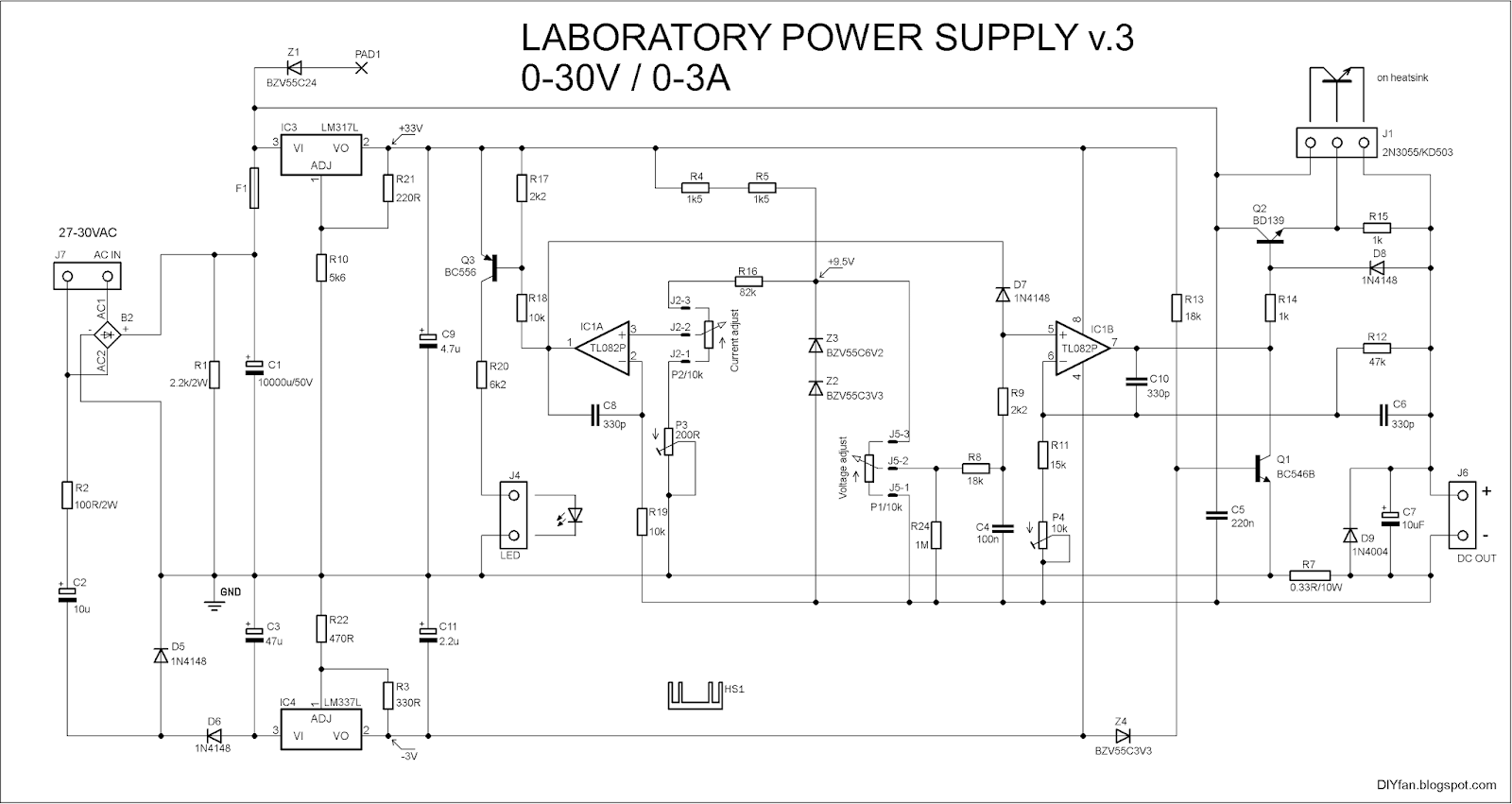

The trimmer P3 adjusts the minimum current limit. P4 adjusts the maximum output voltage. After the final adjustment we may replace the trimmers with standart resistors.
Power transistor must dissipate quite a heat and thus require very big heatsink and maybe active cooling with a fan. We may use two or tree transistors in parallel with emitter resistors to achieve more power.
The rectifier gets very hot when the output current is over 2A, so a small heatsink on top of it will be useful.
The transformer must be 100-120W with 27-30VAC output voltage. You must make some corrections in the schematic if the output voltage is lower or the voltage drop is higher when the current is high. R10 and R21 set the output voltage of the regulator IC3 (LM317) and they must be calculated in such way that the output voltage is 2V lower than lowest input voltage. If, for example, lowest voltage measured across C1 when power supply is fully loaded is 27VDC then output of IC3 must be 25V. With R10 = 4k3 and R21 = 220R we will have that output voltage. With 25V stabilized voltage for ICs the maximum output voltage of the power supply will be around 23VDC.
The schematics will work without these changes but the output voltage will not be so stable.
If the voltage across C1 is bellow 33VDC without load then the IC3 will be unnecessary and we may omit it.
For the current sensing resistor R7 I use two parallel resistors 0.68Ohm/10W. You may use a single 0.33Ohm/10W resistor but it will get too hot.
With R16 = 82k and R7 = 0.33Ohm the maximum current limit adjusted with P2 will be more than 3A - more like 3.3A. If we want to be closer to 3A then the R16 must be 91k.
You may add a 1k linear potentiometer in series to the P1 for fine adjustment of the voltage. Or the better way is using a multiturn potentiometer but they are expensive.
The bizarre looking zener Z1 connected with PAD1 is used to power supply the digital voltmeter which indicates the output voltage. It requires 6-28V supply voltage and with that zener I reduce the input voltage to an acceptable level. Z1 may be omitted if not needed.
I will be glad if other people try this schematic and provide here feedback.
Later there will be link for downloading the project files.
P.S. Here the promised download link:
LabPS v.3 (second schematic)
Inside are PDF files with all project files + partlists.
Use them on your own responsibility.
Update (June 5, 2014)
A lot of people asked me to draw a diagram how to connect digital panel meters. Here how can be connected digital voltmeter and ammeter:

As you can see, in "variant 1" the voltmeter is connected serially to the ammeter, so his supply current will be added to the measured current and will present a very small error (bellow 10mA).
In "variant 2" the ground cable of the voltmeter is connected to the negative output of the board instead of the negative binding post. So his supply current will not be measured, but the voltmeter will display a little higher voltage because the drop voltage at the ammeter (50-80 mV max) will be added.
Make sure the combined supply current of two meters does not exceed 15-16mA (the zener Z1 will overheat).
There was also report, that negative voltage may oscillate. This can happen if the input AC voltage is lower or at high load current it drops significantly. Then input voltage for IC4 (LM337L) gets to low to sustain stable output voltage of -3V. The cure for this is simple: increase the value of C2 to 22 or 47 uF.
UPDATE: 27.01.2019
Link to the original project files for v.3 was fixed.
There is also latest version of the project - couple of small changes and improved PCB. On the board there are places for two different types of negative voltage regulator - LM317 and LM317L. DO NOT MOUNT BOTH - ONLY ONE OF THEM!
The connectors for the power transistor and the input and output voltages are different and more common type than before. Also there are included zipped Gerber files.
>> PS 0-30V v.3.4 <<
>>> I don't give Eagle files, so don't ask me! <<<
Very well! I start first power supply with old schema, but need two power supply.
ReplyDeleteНачал делать блок питания по первой схеме, но их нужно две штуки. Вполне возможно, что буду делать её по последней весрии. Жду схемы. Спасибо!
ReplyDeletePhoto of my power supply.
ReplyDeleteAnd full photos include: in dropbox.
Very nice! I suppose everything work correctly?
DeleteWhat opamp you use?
It's work :) I use RC4558 opamp.
DeleteOne 2n3055 is very tiny for this board. I burned 4 transistors :)
I'm afraid what plastic case melts in big (over 2-3W) ampers.
27 volts out from transformer will 42 volts over rectifier, it's not scary?
If you shortcut the output and there is more than 2 amps then its normal to burn the transistor.
DeleteIf your transformer output is 27VAC it's impossible to have 42VDC after the rectifier.
The formula is Vac*1.41 - 2*Vf where Vf is forward voltage of the rectifier diode.
But even if you have 42VDC it's not dangerous for the schematic, only the output transistor will dissipate more heat and therefore must be cooled adequately.
Thank you Христо :)
DeleteThis comment has been removed by the author.
DeleteI first read your first article about a variable power supply here: http://diyfan.blogspot.de/2012/02/adjustable-lab-power-supply.html
ReplyDeleteand decided to make it :D
But now that ive read this im not sure whether i should build this(v3) or the other one. And what do you think about this one?: http://users.belgacom.net/hamradio/schemas/6-20amps_regulatable_powersupplies_on6mu.htm
it would be nice to have about 6-20A so im considering to make it :D
i meant 6-10A!
DeleteIf you need more amperage then I suppose the schematic in the second link will be more suitable for you. But if you read datasheet of lm317 you will find there similar schematics.
DeleteAnd for the two schematics in my blog I think the second (V3) is better - it will work with common opamps like TL082 and is simpler - with only one chip.
I forgot to mention that if you decide to make that high amperage schematic, you have to use more powerful transformer which will cost more.
DeleteAnd what if i use 2 transistor in parallel, would i need to change some parts or could i use it as is?
DeleteOh and ive got 3x lm395 ( http://www.ti.com/lit/ds/symlink/lm395.pdf , TO-220), 2 in parallel would work, right?
No, I don't think LM395 will work for you, their MAX collector-emitter voltage is 36V which is insufficient. KD503, 2N3055, 2SC5200 will work. In one of the finished modules I used 2SC5589 without problems.
DeleteWhen paralleling transistors you should connect their emitters with 0.27Ohm/5W resistors (like in this image: http://archive.siliconchip.com.au/static/images/articles/i1054/105436_4lo.jpg)
Also if you want higher amperage, then R7 must be with lower value - 0.27Ohm or 0.22Ohm.
What is the Thermal Resistance of your heatsink? I have limited space so i can not get a big heatsink. From calculations i think i need a heatsink with tr <1,5. Oh and ive got some KD502, how many would i need to use in parallel (@ 30V and 3A max output) so that i dont need a heatsink?
ReplyDeleteI don't know the thermal resistance of my heatsink, I just put the biggest that fit in the enclosure. An I also put a fan to help the cooling.
DeleteI don't think there is any possible way to use this PS without a heatsink.
The problem I have is that the enclosure I want to use is relative small (5x9x20 cm), so I need to use the smallest heatsink i can find. Is a transformer with 2x12 VAC and 66VA enough?
DeleteIt depends of what you want to achieve. With 2x12VAC/66VA transformer you will have PS with max 2A and 24VDC output. And of course you may use smaller heatsink.
DeleteAlso if your rectified DC voltage is around 33V or lower, then you may remove IC3 (LM317) and connect a jumper between pin 2 and 3.
I thought you need to divide AC values by 0,7 to get the DC values (voltage and current). So 24VAC rectified and smoothed is 34VDC (minus voltage drop at the diodes) and 2,08A AC is 2,86A DC. Am I right or did I make a mistake there?
DeleteIf your calculations were correct then there would be "free lunch" :)
Delete34Vdc x 2.86A = 97W, but the transformer is 66VA - this is not possible. So if smoothed voltage is 34VDC, then max current is 66W / 34Vdc = 1.94A. It's possible to draw more current, but output voltage of the transformer will drop, and the transformer will overheat.
Hey yo, a great fan of the blog! :) I build my PSU using the second version of the scheme. It worked perfectly. Although I have a few short questions(not about maintenance or debugging or this kind of stuff, nor I will be asking for sch files or so), but I couldn't find email or some kind of way to write directly to you. Can I get in touch with you over email or any other way other than comments here? :)
ReplyDeleteCheers, and keep the good work! :)
You may write me here: xristost in yahoo.
DeleteМоже да ми пишеш на български :)
Maybe somebody can help me. I have transformer which output is 26VAC 2A, and 0-2A regulation enough for me, so I am interested what R7 and R16 resistor value should I use ?
ReplyDeleteThe math is simple. First calculate max voltage drop at R7, Imax x R7. If R7 is 0.47 Ohms and Imax = 2A, then the max voltage drop will be 0.94V. So this must be max voltage at positive input of IC1A. There is voltage divider composed with R16, P2 and P3. Voltage at P2 + P3 must be 0.94V and as voltage at R16 + P2 + P3 is 9.5V then voltage at R16 will be 9.5V - 0.94V = 8.56V.
DeleteR16/(P2+P3) = 8.56/0.94V = 9.1
R16 = 9.1*(P2+P3) = 9.1*10200 = 92820 = 92.82k
The closest standard value is 91k, so R16 must be 91k.
Another way is to change only R7. If you change R7 to 0.47 Ohms then the max current will be 2.2A.
I forget to mention that if your transformer is 26VAC / 2A you can't get 26VDC / 2A at the output. You may try, but there will be excessive ripples at the output.
DeleteThank you for formula and calculation. Probably it will be 0-24VDC and 0-1.5A power supply. Also one more question is V3 version really steable and full working ?
ReplyDeleteI tested it some time and I think it's OK, but I can't guarantee it at 100%.
DeleteHi DIYFAN, I built your version 3 PSU (2nd schematic). I used the LM358 op-amp and it worked quite well. Output voltage can only go up to 27 volts (from 44 volts of unloaded rectified DC from the transformer) maybe because I used an 7809 regulator for the reference (I could not find a 6.2 Volt Zener from my junkbox). Current limiting was lightning fast to not burn a little green LED connected directly to the output terminals at full output voltage (27 volts) at minimum current limit. Really loved it. I have yet to find a case for it though. I hope i can put it together soon as this will be my first proper lab PSU.
ReplyDeleteThank you so much for sharing this design and I wish you much success with this blog!
I am glad everything works as supposed to. If you want, you may give me some photos of your project to post them here.
DeleteAbout the max output voltage - did you adjust it with P4? First, turn the voltage potentiometer to the max position. Then, with P4 adjust the max voltage to the desired value.
If that doesn't work, you may check the output voltage of LM317 - it must be 33V.
And one last note, LM358 has max supply voltage of 32V but in my schematic the supply voltage is -3..+33 which is 4V higher. It's a little risky.
Thank you for the correspondence!
DeleteI'll be glad to e-mail you pictures of my build once I finalized the board, but I have to warn you its a generously horrible hodgepodge of a soldering job (used leaded components for the surface mount parts, as well as, single-turn trimmers and pots, also managed to blow a BC546B and a BD139 along the way because I accidentally shorted a trace). I have yet to get a BD139, the zener mentioned above and additional 0.47ohm carbon resistors (using 10/2watt at the moment, I prefer them to the wire wound ones) to approximate the 0.33ohm current sense. I'm temporarily using a 2SD882 (found in the trash bin) for the BD139 because I only bought 1 when I purchased parts for this project.
I checked the datasheet of the LM358, I guess its output can only go up to 27 volts at absolute max Vsupply, regardless of how I adjust P4. I also checked the outputs of the LM317/337 regulators and they were spot on at 33Volts and -3.3volts respectively. I guess I'll have to source op-amps that you have tested, but I'll steer clear of J-FET input ones because I haven't had much luck with them. Or I'll just adjust the output of the LM317 to be within the safe operating area of the LM358. 26 volts is fine for now, its the current limiting response that's critical, for me anyway.
Sorry for the long reply. Apparently, I'm really enjoying this build.
Again, thank you!
Hi i want to build this circuit but i dint get this BZV55C6V2 diode so can u plz suggest an alternative to this diode....
ReplyDeleteIt's a 6.2V zener diode, you may try to solder ordinary "through hole" zener like BZX55C6V2 or ZD6.2V or 1N5234B or 1N4735A, but it will be better if you find SMD type.
DeleteCLL5234B is exact replacement (SMD, 6.2V/500mW)
Hi! Can i change diod Z4 BZV55C3V3 to BZX55C3V3? Or i will need to change something in the scheme after that? Ths!
ReplyDeleteThey are the same, only the case is different, so yes you can.
DeleteМоже ли да се направи с превключване на намотките на трансформатор, примерно на 15 и 30 волта, с цел облекчаване на работата на крайния транзистор? Трябва ли да се променя схемата? Предварително благодаря за отговора!!!
ReplyDeleteПредполагам, че може да се направи, но не съм сигурен точно как. Може би частта с интегралите ще трябва да се захранва, както е по схемата, а към крайните някакво реле да превключва напрежението. Не знам само в момента на превключване какво ще стане на изхода. Ако решиш да експериментираш в тази посока, ще се радвам да споделиш резултатите.
DeleteИмам няколко идеи и ще пробвам. Само трябва да намеря малко време за експеримента. Ще пиша за резултата!!!
ReplyDeleteHi! I have built your second schematic (V.3) with some minor changes in order to obtain 5A at 30V
ReplyDelete(I've added 3 output transistors in parallel 2sc5200 with 0.22ohm emitter resistors and I've changed R7 to 0.26 ohm / 20W ). I have encountered a small stability problem: at any voltage selected between 0-29,4V and with a 5A load, the voltage stays almost spot on (-30mV), but if I turn the voltage pot anywhere from 29,4V to max (31,5V) when I put a load higher than 2,1A the voltage drops down to 29,4V. Hope somebody could help me with my problem.
This is because the positive supply of IC1 is only 33V and that is slightly insufficient for full 30V/5A. You may try to adjust positive voltage output of LM317 to 33.5V or 34V in order to get 30V output, but the total voltage for IC1 will go little higher than maximum allowed in datasheet (if you use TL082).
DeleteTo do that you must replace R21 with 180 Ohm and R10 with 4.7k. This will give you 33.89V .
And I will repeat: With this modification your supply voltage of IC1 will be higher than absolute maximum voltage noted in the datasheet.
You may replace IC1 with other dual opamp that have higher maximum supply voltage.
Thank you very much for your prompt and very useful response. I've made the changes that you recommended and it worked perfectly. Could you recommend me a higher voltage op-amp equivalent for the TL082 (I've searched on Google for a 44V version of dual jfet op-amp, but I couldn't find one) ? Thanks again.
DeleteYou may use dual versions of opamps used in the other version - TLE2142 or MC34072. These worked up to 44V supply voltage. There is no need opamp to be jfet. The schematic also work well with NE5532, wich have 40V max supply voltage
DeleteThank you again !
DeleteЗдравейте! Схемата работи идеално - изпробвах версия 3. Прекъснах захранването към колекторите на 2N3055 и BD139 и подадох през ключ съответно 12V-18V-24V-30V от трансформатора. Захранването на операционния усилвател/схемата без крайните транзистори/ си остана, както е оригинално по схемата - работи супер и при 3А в различните напрежения крайния транзистор грее съвсем леко. Изпробвах с крушка 12V/60W. Сега остава да помисля за електронно превключване на напреженията с релета и схема с някакъв хистерезис. Забравих да спомена, че трансформатора ми е тороидален около 150W - на който навих вторична намотка с горе-посочените напрежения и с проводник 1,80мм.
ReplyDeleteВъпросът ми е... За да се избегне това дву-полярно захранване, дали няма да може да се използва друг ОУ. Например LM324 или LM358 - те се захранват еднополярно. Намерих доста схеми на лабораторни захранвания именно с LM324 най-вече.Така ще се опрости още повече схемата. Обикновенно я захранват с +15v, за захранване от 0-30V- говоря за други схеми....
Ето един пример: http://smham.ucoz.ru/publ/11-1-0-298
Съжалявам за забавения отговор.
DeleteПревключването може да стане с няколко компаратора от сорта на LM311, които следят напрежението на изхода на потенциометъра P1 превключват съответното реле. Трябва обаче така да се направи схемата, че първо да се изключва едното реле и после да се включва друго, иначе може да се получи окъсяване на намотките на трафа.
Относно захранването на интегралите - направено е с двуполярно напрежение, за да може изходното напрежение да стига 0 волта. Понеже на повечето оп. усилватели най-ниското изходно напрежение е с 1-2 волта повече от отрицателното захранващо, т.е. ако отрицателното е 0V тогава изхода ще е 1-2V.
Специално при LM324 изхода може да стигне почти до 0V при еднополярно захранване, така че предполагам ще стане. Малък проблем е, максималното захранващо е 32V, и съответно максималното изходно ще е 28-29V (според документацията на чипа).
Hi, thanks for such a good write up. Just one thing want to make sure before I start. If I only need the PSU to go up to 12V and I can supply 12V, I will not need the LM317.
ReplyDeleteIf you want your PS to go up to only 12V and your input voltage (DC) is low then you may omit LM317. You must recalculate some elements though. For example IC1B have gain a bit more than 3 so when the input voltage is 9.5V (potentiometer P1 is rotated to max) the output voltage will be around 30V. In your case the max input voltage must be 12/3 = 4V. You may achieve this with simple voltage divider (adding appropriate resistor before potentiometer P1) or replacing two zeners Z2 and Z3 with one for 3.9V or 4.3V. If you replace the zeners then you must also recalculate current setting resistor R16.
DeleteMany thx for your reply.
DeleteAlso, for low current usage can I use a 2N6109 rather than the 2n3055, if I don't go over 1A Max.?
ReplyDeleteChoice of the output transistor depends on max power dissipation required. In worst case scenario when the current is set to max and output is shorted, then the max power dissipation will be Pmax = Uin x Imax. If you have 16V input voltage and max current 1A then the max power dissipation will be 16W. In this case transistor with Ic = 3-4A and P = 30-40W will be sufficient.
DeleteOops my bad 2N6109 is an pnp.
ReplyDeleteHi, I want to build this PSU. But I can't find zeners for Z2, Z3 and Z4. I only have some 6.2V, 9.1V and 5.6V zeners. Also I only have some 10 Ohm 5W for R7. Can you help me please? Thanks
ReplyDeleteHi,
DeleteYou can replace the Z2 and Z3 with one zener 9.1V and the schematic will work, but I am not sure about Z4.
I think 6.2V and 3.3V are quite common values for zeners so it's strange that you can't find them.
R7 MUST be between 0.27 and 0.47 Ohm otherwise schematic will NOT work.
Ok. I will look around some more shops here for zeners. Thanks for your help :)
DeleteЗдравейте! Имам такъв проблем! Като дам на късо за секунда изгаря мощния транзистор - добре че имам повечко от тях. Въпроса ми е, може ли да се изгради някаква допълнителна защита и ако може как? Може ли на мястото на 2N3055 да се постави примерно IRF1010 /Power MOSFET/
ReplyDeleteVDSS = 55V
RDS(on) = 11mΩ
ID = 85A‡ / 180W
Трансформатора ми е с няколко извода, като максималното променливо е 24V/10A. Като цяло всичко работи ОК /регулиране ток-напрежение/ с изключение на защитата. Диода си светва при късо, транзистора въобще не е загрял,но става нещо което немога да си обясня и моля за помощ
Тази схема няма защита, тя има регулиране на максималния изходен ток. Схемата работи като генератор на постоянно напрежение, но в момента, в който тока достигне зададеното ниво, схемата започва да работи като генератор на постоянен ток, т.е. намалява изходното напрежение, така че тока остава постоянен. Светодиода показва смяната на режима, а не че има късо.
ReplyDeleteПри каква стойност на тока изгаря транзистора?
Имай предвид че при късо крайният транзистор трябва да разсее цялата мощност, която е равна на входното напрежение х тока. Ако тока е примерно 3А, а входното напрежение е примерно 33V мощостта ще е 100W, което не по силите на един транзистор, освен ако не е с водно охлаждане :)
Относно мосфета - мисля, че не може да се замени с такъв - мосфетите са съвсем друга технология.
Може да се сложат два успоредно свързани мощни транзистора - колектор с колектор и база с база, а емитерите свързани през 2 съпротивления около 0.2-0.3 ома.
Hey, thank you very much for sharing this great project. I made it and it works like charm. Photos soon...
ReplyDeleteпривет из хорватских :-)
Здравейте отново! Христо, благодаря ти за съвета! Поставих на мястото на 2N3055 един КТ827 и всичко си дойде на мястото. При пълно късо транзистора не гори- пробвах за около минута. Въпроса ми е, може ли в изхода на ИС1А да се свърже светодиод със съпротивление към маса - индикатор за стабилизатор по напрежение, а когато е по ток той да гасне или да намалява светлината си? Не знам дали правилно се изразявам. Също ще ползвам 2 бр. от горните транзистори с изравнителни съпротивления по 0,2 ома и ми се иска да направя схемата до 5А. Закупих един цифров волт-амперметър 50V/5А, който е със шунт съпротивление 0,33 ома. Какво трябва да променя, за да регулирам до 5А, без да променям R7/шунта на амперметъра/? Другият ми въпрос е, може ли да се направи някаква защита- примерно тригерна, например с четвъртия свободен ОУ или пък по друг начин за защита от пълно късо-няма значение дали ще е с реле... Вече работя и по изработката на предния панел, но не знам как да кача снимката - някакви идеи!!!
ReplyDeleteЗа светодиода - според мен той само ще дублира функцията на другия светодиод. Освен това мисля, че може да наруши работата на IC1A ако се свърже директно на изхода. Може да се направи с допълнителен PNP транзистор, който взема сигнал от колектора на Q3 и ще включва допълнителния светодиод когато е изключен Q3.
DeleteДоколкото разбирам, шунта на амперметъра ще замени R7. Тогава, за да нагласиш максималния ток на 5А, ще трябва да се намали R16. Пада на напрежение върху R7 при 5А (1.65V в твоя случай) трябва да е равен на напрежението получено на '+' входа на IC1A, което се определя от делителя на напрежение, образуван от P3 + P2 и R16.
Защита от късо предполагам може да се направи, но това ще изисква доста промени по схемата и аз нямам идея как ще стане.
Освен това къде има четвърти свободен ОУ? Версия 2 ли си направил? Във версия 3 има само един двоен ОУ.
Христо прав си, че като се включи светодиод в изхода на IC1A пречи на работата. Направих и двете версии, но ми се струва, че версия 2 работи по-стабилно. Наистина ще ползвам шунтовото съпротивление на ампарметъра в схемата. Колко трябва да е стойността на R16 за 5А, като трафа ми е както писах по-горе 24V? Иска ми се вместо транзистора да ползвам четвъртия свободен ОУ да управлява двата светодиода / по ток и по напрежение/. Имаш ли някаква идея как да стане? Платката лесно ще я преработя не е проблем? Благодаря ти за отговорите!!!!
DeleteDear Sir,
ReplyDeleteI have built your laboratory power supply circuit version 3. But I am facing some problems at current regulation.
I kept the circuit in proper bias conditions preferred (+33V and -3V at regulators). I used 1 OHM/5W for shunt resistance R7.
At D9, I have used 1N4007 instead of 1N4004, and I replaced C1 with two 4700UF/50V capacitors in parallel. I have listed the results, those I observed below:
**Results taken UNDER SHORT CIRCUIT CONDITIONS of power supply are:
1. Transistor Q2 BD139 emits much heat likely burning, while 2N3055 power transistor lives in room temparature.
2. Resistor R15 1K ohm also emits much heat.
3. 2N3055 transistor was very little hot after a few seconds of under short circuit condition.
4. Only 0.8 Amps max current has been taken.
5. Reference voltage of +9.5V is read as 10.64V. (9.86V under open loop condition)
Please state me out the problem exists, at which part of the circuit? and i have checked the board with part list is correct.
1. Use bigger heatsink for the BD139.
Delete2. Make sure the R15 is realy 1k. Also measure the voltage on R15 - there must be under 1V. If there is more, then 2N3055 is either burned or wrong wired which explains No1.
3. If 2N3055 is wrong wired or burned it's normal.
4. It normal, since you deliberately replace 0.33 Ohm resistor with 1 Ohm. R7 is current sensing resistor and that's why it must be 0.33 Ohm
5. Measure the reference voltage across the two zeners, NOT across the reference point and the ground.
Забравих да спомена, че ще ползвам потенциометри 10к+1к за грубо и точно регулиране на тока и съответно напрежението.
ReplyDeleteАми трябва да се свърже като компаратор - на отрицателния вход подаваш фиксирано напрежение с някакъв делител с резистори, а на положителния подаваш като сигнал изхода от IC1A (през резистор). Когато на изхода на IC1A се получи по-високо напрежение (режим постоянно напрежение), тогава на изхода на компаратора ще има високо напрежение. Ако на изхода на IC1A има ниско напрежение (режим постоянен ток), тогава на изхода на компаратора ще има 0V. За да свети диод при режим постоянно напрежение, трябва да е включен (през резистор) към маса.
DeleteТрябва да измериш на изхода на IC1A колко е напрежението при различните режими и да нагласиш делителя според тези две състояния.
Good evening Христо.
ReplyDeleteThanks for your version of the power supply :)
Tell me please.
What resistors should be replaced for maximum limit of 5 amperes?
I mean, v.3 version of the power supply.
Thank you for your answers!
PS
I will use 3 or 4 transistor 2T827Б in parallels.
The easiest way is to change the R7. With R7 = 0.33Ohm we have 1V drop when the current is 3A. So if we want 5A then R7 must be 0.2Ohm to get the same drop voltage.
DeleteOther way is to keep the R7, but to change R16 to 47k. Keep in mind that power dissipation of R7 will be quite high - 0.33Ohm * 5A * 5A = 8.25W and if you put single 10W resistor its temperature will get above 100°C.
I had built your v.3 power supply. I face the following problem.
ReplyDelete1. Only P1 can adjust voltage from 0-30V. P2 only allow me to get 2 different current value. One is smaller with the current limit LED on, another one is bigger with LED off.
2. I measure the current value with a LED series with a 470 ohm resistor. I only get 60mA and the max current value change when I change the resistor value.
3. The voltage across the 2 series zener diode is around 24V, which = 33 - 9. Opposite to what u stated
4. After I put R13, my voltage output become 0.XXV, which is very small. If I remove this resistor, my output voltage become normal again (0 - 30V)
The above conditions stated after I verified all the transistors and the 2 adjustable voltage regulators. They are all in good condition. Can you help me sort it out?
Thanks
Forgot to state that I'm using 24VAC 4A transformer, but i still get the correct Vo for LM317 and LM337
DeleteI will answer you in same order.
Delete1. If you don't get the correct adjustment of max current then maybe the problem is in your question No3.
2. It's Ohm's Law - it's unavoidable. If you have 30V and drop voltage at LED is around 2V then you have 28V across the series resistor and hence the 60mA you got (which is high for the LEDs BTW).
3. If your zener diodes are correct values and are connected properly it is impossible to get that much difference. When you connect two zeners in series - one 6.2V and one 3.3V, the voltage across two must be around 9.5V. Check again the values of the zeners and the values of the two series resistors R4 and R5.
Probably one of the zeneres is burned out and the voltage you get is because of the voltage divider formed by R4,R5 and P1.
4. The purpose of the Q1 is to quickly turn the output voltage to zero when power is switched off. If you get around 0V when power is on then there is something wrong with Z4. Measure the voltage across base and emitter of Q1. When power is on there must be around 0.3V which is not enough to turn the transistor on.
Здравейте отново!!! Христо, извинявай, че отново се обръщам към теб за помощ, но имам проблем! Тъкмо всичко нагласих и работеше както трябва и се появи следния проблем...Взе да плава напрежението на изхода, губи се и пак се появява...за тока да не говорим. Намерих проблема - дефектирала е LM337 - явно е била фалшива. LM317 не съм слагал , защото ползвам 24 волта променливо засега. Всички други елементи са точно по схемата - направил съм и двете версии. Проблемът е, че не мога да намеря LM337 - в Ловеч имаме два магазина за части, в единия не я предлагат, а в другия съм бил закупил последната от наличните изобщо. 317 колкото искаш... Въпросът ми е, мога ли да я заменя с нещо друго - ценер; някакъв стабилизатор - нещо да върши работа???
ReplyDeleteВарианти има много. Може да се сложи стабилизатор 7905 за фиксирано напрежение -5V, но тогава сумарното напрежение малко ще надхвърли 36V и ако ползваш TL082, както е по схема, има риск от изгаряне. Ако се сложи NE5532 или някоя друга с по-високо допустимо напрежение няма да има проблем.
DeleteМоже също да се сложи резистор свързан след D6 и ценер за 3V или за 3.3V свързан от този резистор към маса. Резистора се смята според необходимия ток и пада на напрежение. Примерно, ако на D6 имаме 15V, напрежението върху резистора ще е 15-3 = 12V. Тока е сума от тока на стабилизация (около 10mA) и захранващия ток за ОУ (около 5mA) = 15mA. Резистора тогава ще е 12V/0.015A = 800ома.
Може да се ползва и варианта от версия 1 (http://diyfan.blogspot.com/2012/02/adjustable-lab-power-supply.html). Там е с два диода 1N4148 (D2 и D3 на схемата), които дават сумарно около 1.2-1.4V. Ако се сложат 4 или 5 такива диода ще се получи около 3V.
hi, i am very new in electronics. i have few question. What transformer i have to use in this circuit? of what amp? and can you please tell me the cap voltage used here??? like i got the 10000uf/50v. but not other ones. Thanks in advance.
ReplyDeletemissed another question. :p in pic and alsso on pcb layout, i can see only a single 0R68/10W (10W0*68JW). but in component list i found R7=2 x 0R68/10W. Can you kindly elaborate what exactly to use??? Thanks.
ReplyDeleteHi, the ideal transformer for this project is 120-150W / 30VAC. Didn't understand the second question "of what amp?"
DeleteThe 10000uF capacitor have to have at least 50V voltage so yours will be fine. The resistor R7 must be 2 x 0R68/10W - if you click on the photo to magnify it you will see that there are two resistors, one is on the top of the other. First one is soldered on the PCB and the leads of the second one are soldered to the leads of the first.
Thanks for the reply. now i see the double resistor after zooming the pic. Understand the transformer type. But for capacitors, what volt rating to use for others then 10000uF? and how can i add any volt and Ammeter to this? i want to add this one :
Deletehttp://www.ebay.co.uk/itm/DC-0-99V-Mini-Blue-LED-Digital-Display-Voltmeter-Voltage-Panel-Volt-Meter-Car-/300902503460?pt=UK_BOI_Electrical_Test_Measurement_Equipment_ET&hash=item460f2fd424
http://www.ebay.co.uk/itm/DC-10A-Ammeter-AMP-Mini-Current-Panel-Meter-LED-Digital-display-K-/360531420750?pt=UK_BOI_Electrical_Test_Measurement_Equipment_ET&hash=item53f158e64e
would you please tell me about this?
This comment has been removed by the author.
ReplyDeleteIf you want to be on the safe side use 50V capacitors everywhere in the schematic.
DeleteAs for the ammeter and voltmeter - i used the same type in my previous power supply and voltmeter was connected that way: black wire to the negative output terminal, red wire via 15V or 18V zener (to reduce the supply voltage) to positive output of the rectifier, and the yellow wire to the positive output terminal. And the ammeter has separate supply and was connected serially to the positive output terminal.
In this schematic there is provided positive supply output for this type of gauges (PAD1 on the schematic). If you want to supply both ammeter and voltmeter from this pad then ammeter must be connected serially to the negative output terminal.
So the black wires must be connected to the negative output of the PCB, the red wires - to the PAD1 and the yellow wire of the voltmeter to the positive output terminal, and the white wire of the ammeter to negative output terminal.
Thanks. I bought most of the components locally. but here is few more question. hope you will answer. :D
ReplyDelete1. 30v / 6A transformer is ok? i dont found anything less than 6A. so di i need to change anything?
2. Components no. R20- 6.2k ohm is not found anywhere locally. instead i got 6.8k. is that ok?
3. LM337L is not available here. but LM337 (Heat sink type) is available. what should i do?
4. I go the flat pin version of KBPC3510 bridge rectifier. not the through hole pin type. but KBPC3506w. can i use that?
sorry for lots of question in one. hope you will answer me. Thanks for the help. And best wishes for your blog, hope will get more project in future. :D
1. Yes, it will be OK. If you use 3 output transistors in parallel mounted on bigger heatsink, then you may go for 5A output current.
Delete2. R20 just limit the current for the LED so its value is not critical. Everything between 3.9k and 6.8k will be OK.
3. The schematic will work with LM337 without problems but the pinout of two regulators are different (Vin and Vout are swapped). You can try to bend the pins or solder little piece of wire to the pins but take care not to short anything. Keep in mind also that the metal tab of the LM337 is connected to the Vin, so make sure it is not touching anything around.
You can also correct the PCB tracks a little. Just cut the two tracks to Vin and Vout pins and solder little pieces of wire to connect them in right way.
4. You can use this rectifier. As for the mounting - you can mount it outside of the PCB and connect it with wires, or solder short pieces of thick solid core wire as extenders of the pins.
I am glad to be of help to my blog readers, so please do not hesitate to ask me any question.
" If you use 3 output transistors in parallel mounted on bigger heatsink, then you may go for 5A output current". what does this mean? im a bit confused. :(
ReplyDeleteThe schematic is designed for 3A max output current. But if you use more powerful transformer as you plan, your max output current can be higher. And because single output transistor (2N3055 or other similar) cannot dissipate this much power, you must connect 3 pieces in parallel. Connecting transistors in parallel is done as shown at Fig.5.1.5 on this page: http://www.learnabout-electronics.org/Amplifiers/amplifiers51.php
DeleteThe resistors connected at the emitters are 0.2 - 0.3 Ohms /5W
You must change also R7 with smaller value - 0.22Ohm or 2 x 0.47Ohm in parallel.
With these changes your power supply can output 5A current max.
This comment has been removed by the author.
ReplyDeleteok. i will use 3 x 2N3055 in parallel, with 3 x 0.2ohm/5w resistor for each. and also a single 0.22ohm/10w resistor instead 0.68ohm/10w. (as i wanted to use a 30volt/6amp transformer).
ReplyDeletei didnt find any smd 18k resistor for R13 & R8 locally. What should i do?
Again thanks for your hearty help. Im really having fun with this project. CHEERS!! :D
I think, that it would be OK to use 22k instead.
DeleteCheers!
I forgot to ask, what fuse i have to use in F1?
ReplyDeleteF1 must be a little more than the max output amperage for example 6A.
Delete0.22ohm/10w or 22k/10w ...... which one? sorry im confused again.... :(
Delete0.22ohm/10W
Delete@pradeep
ReplyDelete90% probability is you have wrong wired 2N3055, based on my own experience with the old version of this power supply.
Hello admin,
I have build this power supply & facing some problems, IC1 Heats up suddenly (I think its when the current control is in action).
The Negative Supply rail drops to -2.5V from -3.1V.
I have checked the supply rail, it is +33V & -3.1V with IC1 Removed. Im using 3.3K + 6.2V & 3.3V Zener configuration to generate the reference voltage which measures to be around 9.8~10V.
I suppose, the transistor Q1 is shorting the output of the OPAMP causing it to heat up.
Also, is it ok to use BC548 instead of BC546.
What is the base voltage of Q1 normally, also can Z4 replaced by a resistor?
Can you please post the voltage measured at different test points under unloaded and loaded conditions. (Especially Q1)
Thanks & regards.
The negative rail must not fall that much. I suppose that is the reason for Q1 to start to conduct.
DeleteCheck the negative supply rail circuit - at the input of LM337L (pin 3) there must be at least -7V. If it is bellow -7V, you can reduce the value of R2 to 82 ohm or increase a C2 to 22uF.
BC548 have low max CE voltage - 30V and it's a little risky. I wouldn't use it there.
The base voltage of Q1 must be around 0 - 0.3V
P.S. check also the AC voltage of the transformer at idle and at load. If it drop drastically, maybe the transformer is not powerful enough?
Hi, questions for you.
ReplyDeleteSo, I built the circuit and turned it on. Definitely outputs power, but it would be nice if it didnt burn up D9. So thats the question, what would cause D9 to burn up? It burned up the 1N4004 so I stuck in a 4 amp rated diode instead(MUR460), that one just burned up too but not quite as quickly.
I already know its very likely a large amount of amperage going through it, I think somewhere around maybe 5+ amps.(as after it blew the first fuse I stuck in a slow blow fuse and that didnt blow immediatly; bypassed the fuse afterwards) After the second diode started to smoke, I cut the power and checked for heating of various parts. It turns out that after only about 10 seconds, the R7 resistors had already reached about 120C, meaning once again, alot of amperage. I was thinking about measuring the amperage(plus voltages), but the thing burns up too quickly. Heres the somewhat interesting part though, nothing else gets hot or burns up; just the diode.(the 2N3055 does get warm as well as Q2)
So the question is, why is this?
Just some info.
Instead of buying a transformer, I modified a computer power supply to output 30V and this gives me the bonus of also providing a 12V power rail for fans(after I modded it, I got 30V on the 12Volts output and 13.5V on the 5Volts; add in a diode and I get about 12.4V for the fans).
I know the computer power supply isnt the problem because I tested it before I hooked it to my circuit.
So, any ideas? I did leave P1 and P2 at half turn(so they would be 5Kohms not the full 10K) for when I first turned it on but that should have been well within tolerances.
For the start, the input of the schematic is 30VAC, so after rectifying and smoothing it gets around 42VDC. If you connect the 30VDC from computer PS to the AC input, the schematic will receive around 28-29V and the max output will be around 22-23V. You can remove the bridge rectifier as the voltage is already rectified and connect these 30V directly to C1 and get 1-2V more output voltage.
DeleteAnd second - there wouldn't be negative supply voltage for the IC1. There MUST be AC voltage so that part of the schematic to work correctly. Without the negative voltage the schematic probably wouldn't work correctly, especially the current control part.
About the diode D9 - it is protecting diode and normally it would not conduct at all because its connected in reverse. So my first guess is that you connected the diode backwards and all the current flowed through it and that's why it burned. And if my guess is right, then its normal that R7 also gets hot.
If your computer PS has -5V or -12V output, you can remove R2, C2, D5 and D6 and connect that negative voltage to the input pin of IC4 (LM337). This will work if (as I suggested above) you connect +30V to the "+" of C1 and the ground from PS to the ground of the schematic.
hello, i've build the 1st one from electronics lab but i've had a problem i've short circuited now it's 0v :( ( yea i'm a newb )
ReplyDeleteisn't the schematic made with short-circuit protection ?
No, the schematic is with constant current adjustment, so when the schematic enter in that mode it will try to maintain the adjusted current. For example if the current control pot is set to 2A and the voltage is set to 20V and we connect 5 Ohm resistor to the output the schematic will enter in constant current mode and will decrease voltage to 10V to maintain 2A current. If we short the output terminals the voltage will be 0V but the current will stay 2A.
DeleteIn your case if the current was adjusted high then maybe the output transistor was burned out.
Hi, first of all i want to thank you for all your efforts in building such a beauty and share it with us. I've just build your Power Supply V3 and it i'm proud of the results!
ReplyDeleteI just wanted to ask you a question about the transformer i'm going to use: I've just salvaged a transformer from an old PSU, it has 2 secondary, one at 36VAC and the other one at 22VAC, with sufficient Amperage.
I would like to know if this transformer is suitable for the schematic.
1) will the schematic work in stable conditions at 22VAC? (i've measured that i can reach 27VDC on the output)
2) Is there a safe way to use the 36VAC secondary or is it too much for the schematic?
Generally speaking, i would like to know which setup will work best, and, in case, which modifications should i make to the board.
Last info, how much did you pay for your toroidal transformer? Where did you get it?
Thanks for all your help man, you're great!
Thanks for good words!
DeleteAnd now for the questions.
1. Probably the PSU will work fine with 27VDC, and you may omit the LM317 (replace it with wire) because the low voltage. Also check the negative rail - if it's lower than 3V, then decrease the value of R2 or increase the value of C2. Everything else should be fine. Max output voltage will be around 22-23VDC.
2. The only problem with 36V will be the high power dissipation from output transistor(s). Rectified voltage will be 50VDC and in the best case at 30VDC/3A output there will be 20V*3A = 60W power dissipation and in the worst case - shorted output/3A there will be 50V*3A = 150W power dissipation. So if you choose to use 36VAC secondary you must be prepared to use at least 3 output transistors in parallel which must be mounted on HUGE heatsink. And all this energy will be lost for heating the air :)
And which setup is preferable - it's your decision.
About the transformers - I order them at local factory (I live in Bulgaria) so I suppose it's not option for you. If I remember correct is cost me around 15 euro/piece
But you can check this site: www.tme.eu - there is large selection of toroidal transformers, for example this will be perfect for the project:
http://www.tme.eu/en/details/58-0125-030-s/toroidal-transformers/talema/
Hi, do you have the eagle files avaiable?
ReplyDeleteHi, first thanks for sharing your work with us.
ReplyDeleteI have 2 questions.
1) Why using 2x0.68 for R7, why not using for example 0.1 for R7 and 300K for R16, than it would be about 1W dissipation on R7?
2) I have couple od BD249 (whitout A,B or C, only BD249), can I use them on 27VAC transformer ?
Thanks.
Hi,
Delete1. If we use very small value for R7, the drop voltage for small currents will be lower than offset voltage of the opamp and the current control would not work well.
2. I think the transistor BD249 will be fine for this schematic. With 27VAC there will be 37V rectified voltage which is lower than max voltage for this transistor.
Hi, and thanks for your work on this PS.
ReplyDeleteI have build this PS using your v3 PCB, and I have done some testing.
I changed LM317 output to 28v (R21=4k7, because of voltage drop under full load), transformer is about 28VAC, and I noticed next:
output 5.000v, no load
if I put load 0.6A I have voltage drop about 10mV, and under 2.8A is about 30mA, that’s not some big problem but I read on electronis-lab forum that max. drop is 3mV under load, and I think that on original schematics is 0.01%. So I checked that 9.5V reference and noticed that there is voltage drop when there is load. I’m note shure why because voltage is also stabilized with LM317, but my voltmeter have 3 decimal digits only from 0-7v, so I can’t check output of LM317 with good precision.
But than I decided to try to stabilize that 9.5v reference using jfet as current limiter, so I removed that 1.5k resistors (R4 and R5) and I have put BF256B instead (like this http://www.hqew.net/files/Images/Article/Circuit_Diagram/fet-led-driver.png) and I have 1mV drop under full load. I have tested that from 5v to 23v (1mV drop under 2.8A load), after 23v I have drop under full load (I note shure why, C1 is having 30v – 1V on R7 – 1V 2n3055 - ???).
Bye
Maybe the current through zeners is low when the supply voltage is lower. When the current is high the voltage across R4, R5, Z2 and Z3 is reduced further with the voltage across R7, so at 2.8 - 3A there will be 27V. Try reducing the R4 and R5 to 1.2k each. This will give you around 10mA current through zeners.
DeleteDon't forget that the output voltage of the opamp usually is 1.5-2V lower than supply voltage unless you use rail-to-rail opamp. That's why you get lower output voltage of PS.
Hi,
DeleteI have read on internet that zener diodes have differential resistance, which means that if current trough zener changes voltage over them change also.
So if there is voltage change at OUT of LM317 there will be change in current trough zener diodes.
If for example there will be 3v change in LM317-OUT there will be 1mA change in current. For 1mA current we can expect about 10mV change over zener, but we have 2 zeners so there will be more change in voltage, maybe 20mV.
And in my case I have voltage drop on C1 under load to 29V (5v output, 2.7A load) . Without load there is 36V on C1, and I have changed R10 to have 31.7V on LM317. So under load I have 29V at IN of LM317 and 27V at OUT of LM317. That’s almost 5v drop. Anyways BF256B instead of 2x1.5k is giving me good results. (I have done this test on 5v out and 1.5ohm resistor)
I'm not electronics engineer and not very good at electronics, I have read that stuf on internet, so maybe I got something wrong.
Hello Sir. A big thankyou for all your efforts with version 2. I built it on vero board and it works like a dream. The current limit is fantastic. I do have one thing that doesnt appear to work and that is P3 setting the maximum current, it doesn't seem to have any effect. I adjust the current to around 3A and turning the trimmer all ways doesn't have any effect on the 3A. Can you confirm the value at 220R and any thoughts would be appreciated. Thanks very much. Regards.
ReplyDeleteHi, the p3 is for minimum.
DeleteD.
Yes, in this schematic P3 is for adjusting the minimum current. The maximum current is determined by R16.
DeleteIf you want to have ability to adjust the max current, then change R16 to 68k and put in series a 50k trimmer resistor.
The P3 trimmer can be replaced with simple 68R resistor.
Thanks for the prompt replies. I would like to adjust P3 for a maximum current output of around 2,5A from the power supply. Should this be possible by adjusting P3 because it doesn't seem to do anything on my power supply build. Thanks.
DeleteI've checked that P3 does adjust the minimum current way down to a few milliamp, just as you said. Sorry, I misunderstood P3's function. Thanks again.
ReplyDeleteFirst to congratulate you on very nice PS V3.
ReplyDeleteI am new in electronic and decide to build this PS - V3.
Unfortunately i cant get voltage more than 10.6 V.
I would appriciate your help.
Transformer is toroidal 160VA 2x24 and i connect secondars in paralel and C1 is 22000 uF/63V
OpAmp is MC 34072 and Q1 is 2N3904. All other components are the same like on schematic V3.
Results:
Voltage over C1 35,8V
LM337 outpoot voltage -2,95V
LM 317 output voltage 33,5V
Voltage accros Z2 and Z3 9,4V
Full turns on Voltage adj. potentiometer give these result on MC34072
pin 1: 33,5 to 33,4V
pin 5: 0.00 to 9,35V
pin 7: 0.00 to 10,6V (after second half turning it drop to 8,15 and stay on that level)
Nothing is heating load
Hi,
DeleteTry to turn trimmer P4 - it adjust the max output voltage. And check the values of the resistors R11, R12 and trimmer P4.
They determined the gain of the IC1B. With these values the gain will vary between 2.88 and 4.13. If you put by mistake 4.7k instead 47k at R12 the result will be similar.
If that doesn't work, measure the voltage at the base of Q1 - it must be lower than 0.5V. If it is higher, then disconnect Q1 to see if the schematic will work without it.
Thank You very much for quick reply.
ReplyDeleteResistors was ok, but suddenly voltage on pin 7 just drop after 10,6. Yes voltage on the base of Q1 (2N3904 in my case jump in same time). As i had surplus BC139 i just replace Q1 with it (there was some wired work on pin swap :) and everything start to work like it should be. Thanks again.
Now i get output voltage 0.002 to 30,91 V.
I stil did not build heat sink for 2N3055 and i made some test where i found current limiter works great.
Unfortunately i only could made test up to 0,5 Amp as 2N3055 was heated like hell. Is it normal that this transistor dissipate so much heat without heat sink even on just 0,5 Amp?
I have one heat sink which have to be drilled and it is nominated on 2,1Celsius over ambient per Wat. (11cm x 6 cm anodised aluminium)
That mean it will reach 120 C on 50Watt.
I would appreciate your help in determining size of heatsink?
I am so happy wit my new PS :)
My question is
I am glad you sort out the problem.
DeleteAnd about the heatsink.
It really depends on how you plan to use the PS. Power dissipation on the output transistor is high when output voltage is low.
If Pdis is power dissipation of the output transistor, Vin is the voltage across C1, Vout is the output voltage and I is the output current then the formula is Pdis = (Vin-Vout)*I
So if the current is 0.5A then Pdis will be between 3W (at 30V output) and 18W (at 0V output). The transistor 2N3055 cannot dissipate more than 1-2W without heatsink and that's why it heated that much. It's a miracle that it didn't burn out.
And to answer the question about the size of the heatsink - if you want the PS to be foolproof then you must use two output transistors in parallel mounted on much bigger heatsink, because if you short the output at 3A current, the dissipation would be 108W.
But if you only occasionally use low voltage and high current and for short period of time, then maybe your heatsink would be adequate.
Hi! I made power supply (PS) ver.3. All ok, but I accidentally shorted collector of BD139-Q2 (collector on heatsink) and "+" output PS. Now, LED is on, and my PS is not working. I can't find what was broken... I tested with ohmmeter 2n3055 - it works, Q1, Q2 works too. I replaced tl082, but my PS didn't work (((( Can you help me? VO on LM317 and LM337 is ok (+33 and -3V).
ReplyDeletewow, i found it... R7 (I use 0.47 Ohm 5W) was burned...
DeleteWhat are the symptoms? What voltage do you have at the output? In what position is potentiometer P2? And is the power transistor heating?
Delete1. Check for shortage at the output - it can be C7 burned and shorted. C7 must be rated at least for 50V.
2. Measure the inputs of IC1A (pin 2 and pin 3). At pin 3 there must be between 0 an 1V as you turn the current adjustment potentiometer P2. At pin 2 there must be 0V if there is no load.
R7 must be at least 10W, and 0.47 is too much for this schematic - you will get max 2A at the output.
DeleteThank you for you reply! I replaced R7, and PS is work fine now. I have not found 0.33R10W yet... I will buy it via Ebay.
DeletePut 2 pieces 0R68/10W in parallel as I did. This way you will have 0R34/20W.
ReplyDeleteHi, now i'm with my problem.
DeleteI change LM317 - it shorted in Vin and Vout, i have true +33 and -3 volts. J1 (2n3055) if fine, Voltage in output is fine, but it is not change if i disconnect J1. Output currency not over 30-40 mA. In J1 in base voltage is fine,
"2. Measure the inputs of IC1A (pin 2 and pin 3). At pin 3 there must be between 0 an 1V as you turn the current adjustment potentiometer P2. At pin 2 there must be 0V if there is no load." - this is correct.
In IC1B pin 6 give 0-30V, pin 6 - 0-10V.
In emitter J1 PS give full power and regulated with potentiometer.
If i turn 1R resistor (for examle) in output, in base of J1 voltage is drop down.
DeleteI found shortcut in D8 (4148).
DeleteIs everything work now?
DeleteYes, now it work. Finally I'm change LM317 and 4148 diode.
DeleteЗдравей, Христо и поздравления за добрата работа! Бях решил да си направя захранването ти и да го ползвам при първоначалното пускане на схеми на аудио усилватели или такива с операционни операционни усилватели, но почти всичките се оказват, че са с двуполярно захранване. Има ли някакъв начин или с някаква модификация да си напрявя и от 0 до -30V? Извинявам се ако нещо съм пропуснал и задавам глупав въпрос, но сравнително отскоро се занимавам с това хоби.
ReplyDeleteЗдравей,
DeleteМожеш да направиш две отделни захранвания и като свържеш "-" на едното с "+" на другото получаваш средната точка (нулата). Така ще получиш двуполярно захранване. Може да се монтират и в една кутия, ако имаш такава с подходящ размер. Разбира се всеки модул трябва да се захранва от отделен трансформатор или поне отделни вторични намотки на един траф, за да няма галванична връзка на масите.Аз така си направих две захранвания в отделни кутии и като ми потрябва двуполярно напрежение или пък напрежение по-високо от 30 волта, включвам и двете и ги свързвам последователно.
Благодаря за отговора! А как се държи захранването при регулиране на тока за малки стойности - например 1-2 mA?
ReplyDeleteТолкова малки едва ли ще може да регулира. Минималния ток се наглася с тримера P3 и зависи от офсета на операционния усилвател. Ако ОУ е с малък офсет ще може да се нагласи и по-малък минимален ток. Мисля че някъде около 10-20 mA е минимума за TL082. Освен това, за да може да се нагласят фино подобни малки токове, потенциометъра P2 трябва да е многооборотен иначе малко като мръднеш копчето и тока се променя с много.
DeleteТова с многооборотния потенциометър и ОУ с по малък офсет може да го пробвам как ще се получи. Всъщност ако по този начин държи стабилно токове между 5 и 10mA, пак ще ми върши работа и ще съм много доволен. Относно операционните усилватели дали нещо като OPA2277 или AD708 ще работи на това място? И двата ОУ са с много нисък офсет и дрифт, по два в корпус PDIP8 и могат да бъдат захранвани с напрежения до +-18V.
ReplyDeleteСтрува ми се леко "изхвърляне" да се ползват подобни скъпи части, но ако имаш мерак, защо пък не :)
DeleteБи трябвало да работят без проблем.
:) Е, ако нямах нужда от по-голяма прецизност при малки токове...бих направил схемата точно както си я дал. Но така или иначе ще пробвам първо да подкарам захранването както си е, пък после ако се налага ще подменям ОУ-та и потенциометри.
DeleteHello thank you for this beautiful project,I have created power supply v.2 but I am a litle bit stuck.I have a several question.
ReplyDeleteInput Transformer is 36V 8,33 A .I have don a litle modification on input of LM 317 so now the input voltage is 35,2V becaus max. input voltage 37V .
1. how to adjust minimum curent limit with trimmer P3 ?
2.What should be a value of R7 if I want to have output curent 0-8A
3.I use 5 x 2n3055 mounted on heatsink 35cm x 24cm x 3cm is that ok?
Thank you and best reguards from Croatia. :-)
Hi,
DeleteI think the transformer isn't very suitable for this project. Let's make quick calculations: the rectified voltage will be 36x1.4 - 2 = 48VDC. In the best case when the output is 30V and the current is 3A, the amount of heat produced by output transistors will be (48-30)*3 = 54W. If current is 8A then the heat will be 144W. At 12V/3A output heat will be 108W and 12V/8A - 288W.
And if you short circuit the output at 3A the heat will be 144W and at 8A will be 384W.
These numbers are insane :) you must cool the whole PS with some sort of liquid cooling. I doubt your heatsink will do the job at the extreme cases.
But, of course, you cant try...
The minimum current is adjusted with the current potentiometer P2 set at minimum. Then we adjust the P3 to the minimum level at which LED is not turned ON.
The max voltage drop at R7 is around 1V, so if we want 8A, then resistance is calculated with Ohm's Law, R = U/I. In your case, R = 1/8 = 0.125Ohm
BTW, the LM317 didn't have max input voltage. It have max input-output voltage differential, which is 40V.
I have trouble when charging accumulators, 4148 diode closing. Max output current is lower then 1 amper.
ReplyDeleteI change it to 1n4002
DeleteI don't know what function have this diode, probably some protection from reverse voltage. The other version of the power supply doesn't have it at all, so I don't think it is critical part. Check is there any current flowing when the accumulators are connected and the PS is OFF.
DeleteAnd an advise - there are simpler schematics for constant current that are more suitable for charging accumulators.
Hi.
ReplyDeleteThere is chance to get voltage drop on -3 out from LM337 because of low C2 value 10uF. 47uF for C2 is better value. When there is voltage drop on -3v line then Q2 turns on and shut down output, then -3v recovers and we have bad oscilations. You can see that only on oscilloscope. Oscillation are visible when current protection is on.
D.
Maybe if the AC supply voltage is lower that can happen. So the some of the parts of the project must be recalculated if supply voltage is lower.
Deleteif I use a shunt 0.01 or 0.1 ohms?
ReplyDeleteSo, what is your question?
DeleteIf you ask can you put 0.01 or 0.1 ohm at R7, the answer is yes, you can.
But what is the point?
Колега, Васко от Пловдив ли ти навива трафовете, или си ги поръчвал от нейде другаде?
ReplyDeleteСъщо така искам да та питам - негде из коментарите мерках някой да пита мое ли да се адаптира кат' зарядно въпросната схема, но ти си го наредил набърже и си отфърлил предложението. Можеш ли да предложиш някаква друга достатъчно читава и проста (в смисъл - да се събере на малка платка освен 1 или 2-та pass транзистора) която ефективно да е стабилизатор на две фиксирани напрежения (примерно със ЦК ключе за 7.2V и 14.4V) със регулируем ограничител на тока примерно 0-5A ? Ъммм ... и ако може да е със сравнително ниска стойност енерго-ядящото токо-следящо съпротивление (тия двата 10-ватовите бойлера).
Поздрави, Ники! :)
Трафовете са правени по поръчка от Novatech. Преди време съм купувал от Васко, ама той взима малко скъпо пък и трябва да се плаща и доставката.
DeleteСъс зарядни не съм се занимавал, ама сигурно има хиляди схеми по нета. Ако трябва да се зарежда автомобилен акумулатор, захранващото напрежение трябва да е по-ниско (предполагам 15-20VDC), за да не се губи излишна енергия и да се отделя много топлина.
Привет. Скажите, как изменить схему, если я буду питать от импульсного блока питания. Если будет постоянное напряжение, нужно убрать диодный мост. А как быть с цепочкой: R2 C2 D5 ?
ReplyDeleteМой русский не очень, так что извините :)
ReplyDeleteЕсли хочите питать схему с источник постоянного напрежения, то надо позаботится для отделного източника отрицателной напряжении. Ето можно быть отдельний маломощный трансформатор или отдельной намоткой основного трансформатора.
Есть тоже какие-то ИС для преобразования положителного напряжения к отрицателном, например ICL7660. Если мы соединим дополнителный LM317 так, что выходное напряжение было например 9V, тогда с этой ИС ICL7660 мы получим -9V, которые надо подключить к входу IC4 (LM337).
Это будет сложно для меня. Буду искать трансформатор. Спасибо :)
DeleteКстати ваш русский не так уж и плох, я все понял)
Я попробую использовать транс от ИБП от APC, 12в на выходе, 2 плеча (24в) и попробую использовать несколько транзисторов TIP3055 для увеличения мощности, говорят, он немного лучше себя ведёт.
DeleteЯ нашел советский трансформатор ТС200 и четыре транзистора КТ819БМ. Начинаю с перемотки трансформатора :)
DeleteХристо, выложи, пожалуйста, негатив схемы, Нужен для фоторезиста.
ReplyDeleteВ архиве есть негатив PCB - PSU0-30V_V3 (copper mirrored).pdf
DeleteНе, это не то. Нужно чтобы белое было чёрным, а черное - белым. Как эта http://0.tqn.com/d/painting/1/5/d/W/1/NegativeSpace-Vase.jpg
DeleteКакой фоторезист изпользуешь? Я делаю мои платы с фоторезист POSITIV20 и для етого мне не надо такой негатив.
DeleteВо, у тебя Positve20, а у меня negative (негативный плёночный Ordyl Alpha340) :) ладно, разобрался уже.
DeleteHello. Help me please. I did ver.2. Voltage always show zero =(.
ReplyDeleteAfter lm317 31V, lm337 -3V, IC2 pin2 has 9.1V. Led current limit switch on max P2.
I tryed to change TL082 and bd139.
Now i don't know what to do...
Check the voltage between the base and the emitter of the Q1 - must be below 0.4 V so the transistor must stay off when power is on. If there is higher voltage the the transistor is on and effectively shorting the output of IC1B. If this is the case, the IC1 probably gets hot. You can try with another zener diode Z4 with lower voltage - 3V, or 2.4V
DeleteCheck the output voltage of IC1B - if there is any voltage and the output of power transistor is 0V then the problem may be in the driver transistor BD139 or the power transistor. And if the current limit is ON then maybe there is some shorting in the output.
Voltage between the base and the emitter of the Q1 is 0.3V. IC1 not hot.
DeleteOutput voltage of IC1B is 1.3V, but output is 0V. The last what to do is try to change 2n3055.
Is the voltage at the input of IC1B (pin5) change when you rotate the voltage adjustment potentiometer P1?
DeleteIf not then maybe IC1A is turning ON the current limiting for some reason. If that's the case, check voltages at the inputs of IC1A - pins 2 and 3. If nothing is connected at the output terminals, then at pin 2 must be 0V and at pin 3 voltage have to change from 0 to 1V as you turn current limiting potentiometer P2.
The voltage at the input of IC1B is 0V and not change then rotate P1.
DeletePin 2 is 0V. Pin 3 change from 0V to 0.9V then I rotate P2. But then I touch pin 2 by multimeter the limit current led is turn on.
I forgot to ask - what is the voltage of the output of IC2A (pin1) - it must be 9.4 and at pin2 you must have 3.8V and not 9.1V as you wrote in the first post.
DeleteCheck again carefully all voltages at inputs and outputs of three opamps.
IC1A:
pin3 must be from 0 to 1V (or 0.9)
pin2 - 0V if there is no output current.
pin1 - must be high, more than 10V
IC2A
pin2 - 3.8V
pin3 - 3.8V
pin1 - 9.4V
Hello.
DeleteIC2A:
pin1 is 9.23V
pin2 is 3.7V.
IC1A:
pin1 is 30V.
pin2 is 0V.
pin3 is from 0V to 0.9V.
IC2A:
pin1 is 9.24V.
pin2 is 3.71V.
pin3 is 3.69V.
Now, if output pin of IC1A is high, then there is no reason at pin5 of IC1B to have 0V. This pin get variable voltage from P1, which get 9.24V from pin1 of IC2A. Check voltages at 3 terminals of P1 You must have 9.24 at upper pin, 0V at bottom pin and variable voltage at middle pin. If not, check the potentiometer, or cables connecting him to the board.
DeleteI lost so much time to find a problem and it was potentiometer P1, it is not work. I checked it before installing and it was fine. Now Supply Power work!!! It's WORKS!!!
DeleteTHANK YOU A LOT.
Shortcut circuit works to. Max voltage is 29.1V. Can it be because i changed R10 to 4k7 and R21 to 200R (R21 I don't have another value). Voltage now after LM317 is 31V and was before change 34V.
Thank you once more. You very helped me.
I'm glad that everything work now. For R10/R21 you can try these combinations - 4.7k/180, which will produce 33.9V after LM317 or 5.1k/200 for 33.1V. But that's only in case you really have to have 30V :)
DeleteА вместо LM337 что можно еще поставить? нигде найти не могу... Ради одной детали делать заказ в интернет магазине не выгодно...
ReplyDeleteThere are voltage regulators from Linear Technology, for example LT1964 or LT3015, but they aren't very popular. Another way is to replace the IC regulator with simple "zener - transistor" schematic, like this one: http://modeltrainadvisors.com/voltage-regulators.html (second schematic in the page). And you can use simple zener diode regulator which is only resistor and zener.
DeleteEще один вопрос.. на входе с трансформатора поле выпрямления у меня 27V, а на выходе 24V.. Это нормально? или можно повысить вольтаж на выходе? я использую TL062.
DeleteЕто нормально. Мы имеем 1 - 2V потери в LM317L, 1-2V в TL062 (максимальное изходящее напряжение на 1-2V менее чем напряжение питания). Если выпрямленое напряжение с трансформатора менее чем 33V, можно удалить LM317 и связать напрямо с куском проволоки. Но выходное напряжения будеть менее стабильное.
DeleteHi.
ReplyDeleteJust tested mc33078, and it's working fine.
HI,
ReplyDeleteCan i use a negative 5v regulator instead of LM337 ?
Yes, you can, but with 5V negative regulator you will have 38V (33+5) total supply voltage for the opamp. Check in the datasheet if your opamp will withstand it. TL082 cannot, NE5532 will do the job
DeleteHello and thanks for fast answer,
DeleteI have several TL072 and LM358. They should not work too...
Can i reduce the +33V voltage from the LM317 to compensate ?
Thanks,
Hi,
DeleteYes, that is a possible solution, but keep in mind that max output voltage will be reduced with the same amount.
Another solution is to wire 3 diodes serially at the output of the negative regulator (I suppose it's 7905? ) thus reducing the negative voltage further with 1.8 - 1.9V. That's way you will have -3.1V, which is close enough.
OK ,
DeleteAs i have plenty of 3V3 and 33V Zener diodes, i will replace both regulators (that i don't have) with Zeners + transistors.
I think regulation will be good enough ?
Thanks again,
Yes, the original schematic is that way. I replaced the transistor/zener combination with LM3xx to simplify the schematic. Of course LM3xx have better regulation and various protections, but in the end this isn't that important.
DeleteHello sir,
ReplyDeleteThank you very much for documenting this project! I hope to build a PSU based on your design.
And now for my first question. I don't seem to be able to find the power ratings for the diodes D5, D6, D7, D8 and D9 in the V3 schematic. Would you mind helping me with those?
ReplyDeleteThank you.
Just search the datasheets of these diodes - they are the most ordinary: 1n4148 is small signal diode and 1N4004 is 1A rectifier. Two of the 1N4148 are SMD and can be used SOD123 or MINIMELF packages, the rest are in standard through hole DO-35 package. The 1N4004 is in through hole DO-41 package.
DeleteThank you Христо,
DeleteI'm in the U.S. and I have been able to find all the components except for the connectors you used for J1, J6 and J7 (Oh, and the transformer but that's for another time). I can't seem to find any board to wire connectors like you used. Any suggestions?
I used these, because they are narrow, they are rated 7 Amps and 3 pin variant have direction i.e. cannot be connected wrong way.
DeleteHere the manufacturer web site: http://www.cvilux.com.tw/product.aspx?lang=en&pid=807
Of course you can solder cables directly to the board if nothing else work.
Awesome! Thank you very much.
DeleteHello again,
DeleteThree quick questions:
1. Are there any differences between C2 and C7 other than size?
2. What size and voltage LED did you place at J4? It looks like a 5mm.
3. I don't see a resistor after the LED and I'm not good enough at reading schematics to figure out what voltage is going to J4. Is it ok to use an LED here without a resistor?
Thank you!
1. For C2 I chose bigger package, so there may be soldered capacitor with bigger capacitance, 22uF for example. This is in case the negative rail is not stable enough.
Delete2. It's your choice - any LED will do the job. That's why there is connector - you can connect with cable any LED - red, green, 3mm, 5mm, and place it on the front panel.
3. There IS resistor in series with the LED - R20. It is calculated for about 5mA, but you can replace it with smaller value to increase the current. But don't forget to calculate the power dissipation of that resistor and put one with appropriate wattage.
Thank you Христо!
DeleteSo I guess that means there is approximately 30v going to J4. Now that I look at the PCB that figures. Ok. I found all the components for the PCB. I just have to find a case, heat sinks and the Voltage and Amperage panels. I feel like such a mad scientist. I'm going to scream "IT'S ALIVE" when I finally fire it up!
Thanks for all the help. Wonder how much a beer costs in Euros?
Not exactly 30V. There will be 30V only if the LED is not connected. If the LED is connected to the J4, then voltage will be decreased by R20 to 1.7V - 3V (depends on the LED type).
DeleteGood luck!
P.S. Here in Bulgaria a beer costs 0.5 - 1 euro :)
Hello. First of all, I want to thank you for so well documented PSU and all answered questions.
ReplyDeleteI will start building one for myself (second sch), but first I have some questions.
1) Resistor R1 is bleeding resistor, am I right?
2) What is purpose of R4 and R5? How are they affecting on 9.5V reference?
3) If I put two or more parallel power transistors, why is there should be small resistors on their emiters?
4) If I got it right...when you turn on PSU, transistor Q1 get some voltage (I assume 0.3V, based on 3.3V zener Z4 connected on -3V) and opens...so basically it connect IC1B output and R14 to the ground?
Thank you.
Hi,
Delete1. Yes.
2. I put two resistors to share the heat, because the power dissipation for 1206 package is 0.125 and there will be more than that. One of my readers suggests to replace the resistors with constant current source with one JFET transistor. The only problem is that JFETs are rare animals these days :)
3. The purpose of the emitter resistors is to level the currents of the transistors.
4. No, 0.3 V is not enough to open the Q1. When the power is turned off, the negative rail go down (usually quicker than positive), the Q1 will open, shortening the output of the opamp to prevent any unwanted fluctuations in the output. This will last only couple of seconds, so there is no danger for the opamp.
This comment has been removed by the author.
DeleteThank you.
DeleteI have couple more questions. :P
1) What is purpose of diode D8 and capacitor C4?
2) I have noticed that lower part of voltage reference circuitry is not connected to the ground, but on sense wire of resistor R7. correct me if I´m wrong but when there is no load connected on output, there is no current through R7 therefore this sense wire is practically on ground. but when you connect load and current flow e.g. 3A, there will be 3A x 0.33R = 1V. so then reference voltage will be 10.5V and op amps will have 1V error. now it`s a bit of mess in my head and I`m trying to understand it :)
3) can I remove P1 and P2 so I can feed op amps with some externally controled voltage signal form DAC or any other source?
4) how precise is constant current LED signal. does it show exact moment when constant current regulation kicks in?
5) what if I change this LED with some that lights up on lower voltage? is there need for some recalculations of R17, R18 or R20?
6) is better solution to put soft-start resistor before or after transformer?
7) does op amp starts to heat up on higer output currents?
I`m sorry if I bother you, but I want to understand this circuit as much as passable.
I`ll try to upgrade it with some relays on input and output with thermal and over voltage protection.
I have learned so much just by reading all this Q&A.
Thank you again :)
1. I don't know about D8 - maybe protection of some sort. C4 is noise filtering, I think.
Delete2. You are partially right. Reference voltage is connected to the "output" ground, but the inputs of IC1B are also referred to this artificial ground point and that's why there will be no error in the output voltage. The IC1A input are referred to real ground, so there will be difference of reference voltage between "no load" and "load". But this is not that important for the current limiting. This can be solved with another voltage reference.
3. Of course you can.
4. I am not sure - this can be viewed only with oscilloscope.
5. The voltage of the LED doesn't matter that much, the current does - R20 is calculated for 5mA.
6. Soft start usually is put before transformer. But for 120-150W transformer I think there is no need for soft start.
7. I haven't tested it with high load for long period so, I can not tell. The Q2 and the output transistor must be selected with high current gain to reduce the output current of the IC1B.
This comment has been removed by the author.
ReplyDeleteПривет Христо!
ReplyDeleteХочу поблагодарить за отличную работу!
Прошу совета
Получил с ebay 1n4728a 3v3 вместо bzx55c3v3 у них Istab.min 76ma
На Z2 2.1v на Z4 2v вместо 3.3в маленький ток нет Ustab диод не работает. Изменение R4 R5 R13 помогут?
Новый заказ ждать 3 недели очень не хочется. Спасибо
I don't think, the problem is in the zeners. 76mA is the test current, not the minimum current. In the datasheet the minimum current Izk = 1mA, and there must be 7.8mA (if the voltage at LM317 out is 33V). Make sure you are soldered the zeners in correct way.
DeleteI don't recommend increasing the current with changing R4 R5 R13, at least not much, because the LM317L and LM337L are not designed to dissipate much power.
If your zeners are soldered correctly, you can solder temporarily an resistor in parallel to test if there will be difference. For example if you solder 10k resistor in parallel with R4+R5, the current will increase to 10mA, with 4.7k there will be 13mA.
And R13 indeed is little higher. You can try with 10k or 9.1k
Hi afraid i am such a noobie i still have my wrapper on. I am interested in building your V3 power supply. I wondered if you give advice please.
ReplyDelete1. What size SMD' do you use for the circuit?
2. Are the through hole resistors 1/4W?
3. I have read about making a rectifier with diodes and all i have seen dont have any cooling. Can yours be built the same way?
4. I would like to use digital readouts- separate Ammeter and Volmeter. Could you let me know how i wire them in?
5. I have seen a toroidal on ebay, 120VA with 0-30 0-30VAC outputs. Is it the correct one or will i have to modify anything? If i do could you guide me as to what?
Many thanks for reading and a million thanks if you can help.
Hi,
ReplyDeleteI am glad you find this project interesting.
As for your questions:
1. All SMD resistors and capacitors are 1206 size and diodes are minimelf or SOD-123 (they are interchangeable)
2. Most of the TH resistors are 1/4W
3. If you replace the rectifier with diodes, make sure to leave them with long leads. Even with long leads however they will heat as hell. I have tried with these: http://www.rectron.com/data_sheets/10a05-10a10.pdf and they do the job perfectly but I haven't test them in long run.
4. I will post connection diagram here these days.
5. It will be fine. There are to options for this type of transformer. If the two windings are identical then you can wire them in parallel. You can measure if they are identical connecting "0" of one winding with "0" of the other and measure the AC voltage between the other two leads. If the voltage is 0VAC (or very close) then you can wire them in parallel ("0" with "0" and "30" with "30"). If there are bigger difference then there will be some unwanted equalizing currents which can heat up the transformer.
The better option is to wire the windings in series and rectify the voltage with two diodes only as shown here: http://en.wikipedia.org/wiki/Rectifier#Full-wave_rectification
Of course connecting to the PCB will be different, because you must connect 3 wires to the board, not 2. I will make some drawings how to connect all in couple of days.
Thank you so much for taking the time to help and your prompt reply. You are amazing. Its obvious you have a great passion for electronics and for passing on your superior knowledge. I have copied the specifications and included them below.
ReplyDeleteDimensions (mm) 100 (diameter) x 43
Power Input 220-240 VAC @ 50 Hz
Outputs 0-30,0-30 VAC
Power (VA) 120
If i can supply 2x30v i would like it to supply two units. This would be just a case of providing two identical circuits and placing in a case big enough for the parts. lol If you don't think it is the correct transformer please advise on where to get one.
Again many thanks
This transformer can supply two units, but with reduced output current. As it has 120VA power rating, then for one unit there will be 60VA. Rectified and smoothed voltage will be around 40V. Then the max output current will be 60/40 = 1.5A. If this satisfied you then go for it. But if you want to get full 3A output current, then you must find similar transformer but with 240-250VA power rating. Or you can get two transformers of this type and each unit will have separate transformer. You can mount them one over another to save space in the enclosure.
DeleteThank you my friend. I have searched all over and cannot seem to find anything suitable at a reasonable price. If anyone could help it would be very much appreciated. Many thanks for all your time.
ReplyDeleteRegards
If i cannot find a suitable supply for two boards, am i right i can get the full 3 Amps 30V with the transformer but it will only supply one board? If so do i have to change any components?
ReplyDeleteSorry to trouble but really trying hard to learn and understand.
Regards
Try this site: http://www.tme.eu/en/details/tst250w_2x28v/toroidal-transformers/indel/tst250023/#
DeleteDon't know how much will be shipping for you, thou.
Hi my friend, sorry but i do not know your name. I have seen this and is £38 delivered. CM0300230 Specs are, 300VA 230v to 2x30v. Would this power two units? would i have to change anything? A million thanks as usual for everything.
ReplyDeleteYes, 300VA will be fine, but get sure the transformer has two SEPARATE secondary windings and not center tapped because if the transformer is center tapped you can't connect the "+" of one unit to the "-" of the other to form a split supply (i.e. -15 0 +15V for example).
DeleteAgain many thanks for your prompt reply and advice. I have just sent them an e-mail to confirm.
ReplyDeleteHello Христо,
ReplyDeleteI'm trying to decide what potentiometers to use for the voltage adjustment. If I have been reading correctly I can use a 10 turn pot for the voltage adjustment. If I do that I wouldn't need to use the extra "fine tuning" pot. Is this correct?
Thank you.
Bradford
Yes, that's correct. I, myself bought recently from ebay some 10k multiturn potentiometers, but haven't install them yet.
Delete