Showing posts with label DIY. Show all posts

Friday, June 2, 2023

Mini sine wave oscillator

This project is a variant of the 'Miniature Audio Oscillator' by the great Rod Elliott.

I have made very few changes to the core schematic. I removed the potentiometer used for adjusting the frequency and replaced it with a DIP switch, allowing for easy switching between three different frequencies: 20 Hz, 1 kHz, and 20 kHz. These options should be sufficient for quickly testing various audio equipment.

Additionally, I added a third dual opamp. One half of the opamp is used as an output buffer, while the other half serves as a voltage rail splitter and virtual ground. The schematic is designed for a single rail voltage: a 9V battery should be sufficient, but it can also work with higher voltages up to 30V (depending on the opamps used). If Li-ion batteries need to be used, then it is recommended to connect 3 or 4 batteries in series.

The output signal, as stated in the original article, has very low Total Harmonic Distortion (THD) at approximately 0.12%. While I do not have the necessary measurement equipment to gauge the distortion of my variant, I estimate it to be below 0.5%.

I created this project using the EasyEDA software, with the aim of making it relatively easy to replicate at home. The design employs a single-sided PCB and through-hole components.

This is the schematic:

And this is 3D view of the PCB:

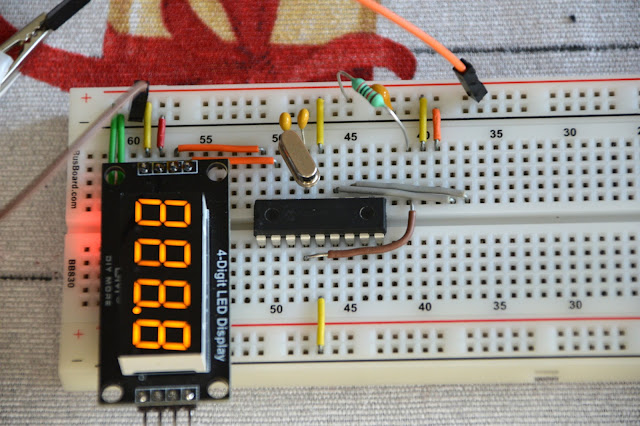
For this project, I used a photosensitive dry film for the first time. It wasn't easy, but after a number of trials and errors, I finally managed to produce a fairly good PCB. Here's how it turned out:


The oscillator utilizes a 4-channel DIP switch to control the activation of different value capacitors, thereby altering the output frequency.

The formula for calculating the frequency is F = 1 / (2π × R × C),

where R = R6 = R7 = 10k and

C = C1_A = C2_A = 680 pF when all switches are OFF. These two capacitors can also be 820 pF. To achieve a frequency close to 20 kHz, I handpicked two 680 pF capacitors with higher actual values.

When the left two switches are ON, C = C1_A + C1_B = C2_A + C2_B = 680 pF + 15 nF ≈ 15.7 pF.

When all switches are ON, C = C1_A + C1_B + C1_C + C1_D = C2_A + C2_B + C2_C + C2_D = 680 pF + 15 nF + 680 nF + 100 nF ≈ 795 nF. Note that C1_D and C2_D are included for fine-tuning the lowest frequency of 20 Hz. While not strictly necessary, omitting these capacitors will result in a slightly higher lowest frequency, around 23-24 Hz.

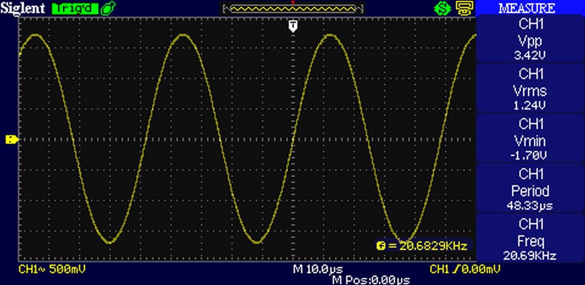
The output voltage measures approximately 3.5 Vpp or 1.24 Vrms and can be adjusted with the potentiometer.

The schematic is compatible with various types of opamps. I tested it with TL072 and NE5532. The current consumption with the TL072 is approximately 10-11 mA, whereas with the NE5532, it is around 34 mA. For extended battery life, the TL062 is the optimal choice; however, I do not have any available at the moment. With the TL072, the output signal begins to visibly distort when the supply voltage drops below 8V.

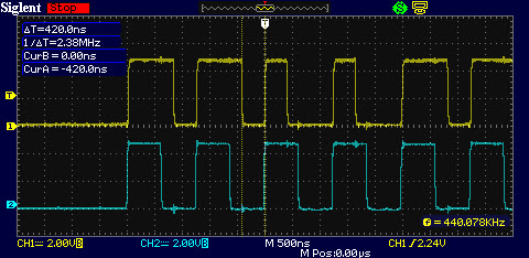
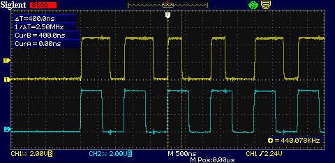
Here some screenshots from the oscilloscope:


And here is a video of the oscillator at work:

Project files can be downloaded from here: MiniOsc. Use them on your own responsibility!


Wednesday, April 6, 2022

Driving NeoPixel type ARGB LEDs with PIC

 I have ordered 10 pcs of addressable LED from Aliexpress some time ago and tested them with my Arduino boards and the library from Adafruit and they work as expected. But of course I am more a PIC guy, so I start to thinker with some PIC microcontrollers trying to drive these LEDs. And it is not easy! So the major difference between 8-bit PIC micro and a ATMEGA 328P is that the ATMEGA command rate of ATMEGA is the same as clock rate, so it has 16 MHz clock frequency and 16 MHz command rate but the PICs have command rate 4 times slower than clock frequency. So a PIC clocked at 16 MHz will have 4 MHz command rate and 32 MHz PIC will have 8 MHz command rate. In order to achieve similar performance as ATMEGA, the PIC must be clocked at 64 MHz. 

The difficulty comes from the very high frequency and the format of the output signal. The frequency of NeoPixel signal is ≈800 kHz and the "1" have 800 ns high followed by 400 ns low. The "0" is 400 ns high followed by 800 ns low. And 1 instruction of 32 MHz PIC microcontroller take 125 ns to execute. It is impossible to write a C code that can create such signal in 9-10 instructions. This is achievable only with carefully written Assembler. I had success with PIC16F1847 clocked at 32 MHz.

It was pain in the a**, because there are very little info and tutorials about writing mixed code (C and assembler) for xc8. For example I couldn't find a way to declare a variable in BANK0 in assembly code because the variables in C code evidently take precedence and occupy all the free space in BANK0 first. And it is important the variables to in the same memory bank as PORTB, because changing banks takes one additional instruction. So I has to declare the variables in the C code specifying the exact address... 

The above code has two subroutines _sendByteASM and _sendByteASM2. The first one use a cycle to check and send the bits to the serial output pin (in this case RB4). The best timing I was able to achieve this way was "0" - 375ns/875ns, "1" - 875ns/500ns. And it worked.

The second subroutine check and send every bit separately and there I was able to achieve timing much closer to the required. "0" - 375ns/875ns, "1" - 875ns/375ns. 

Then I got a more modern PIC - PIC16F15344, which have 4 very interesting modules: Configurable Logic Cell (CLC) each of which can be set as 4-input AND, AND-OR, D-type flip flop, J-K flip flop and couple of other types. Also I saw a video from the great Ben Heck where he is using the SPI output from ESP32 with some external logical chips to form the output signal compatible with NeoPixel. 

My thought was to feed the color bytes to the SPI module (configured to work at 800 kHz) and the output (clock and data) to use somehow to form impulses with different length and then combine them with CLC. The following screenshots are the settings of different modules used in this project.

The CLC1 is configured as AND-OR and the signal from the SPI is directly routed to the output. This will be needed later. 

For creating the waveforms of "0" and "1" I used the Complementary Waveform Generator (CWG). This module is used to create a signal for driving half-bridge or full bridge circuits and among other setting there can be set a dead time. So I fed the signal from CLC1 (which is a copy of SCK signal and have 50% duty cycle or 600 ns high) to the CWG module and set the dead time of the rising edge to be about 400 ns and when inverted this will be the "0". The dead time of the falling edge is set to be around 200 ns increasing low time to 800 ns and when inverted form the "1" waveform.

CLC2 is configured as 4-input AND. There I combine the inverted output from CWG1A, CLC1 and SDO from SPI to create the "0" signal:

Finally, all is combined at CLC3 which is set as AND-OR cell:

Here the inverted signal from CWG1B is "AND"-ed with the SDO signal to produce the "1" signal. Then both "0" (from CLC2) and "1" are "OR"-ed to form the final output signal which is routed to one of the pins - in my case RC4/pin6. 

Here some scope screenshots:

The timing here is much better and the beauty of this solution is that there is no interrupts, no assembler code. All of the above is just setup of registers. I am using MPLAB Code Configurator to generate all the code and the actual work is done by the hardware modules and for sending a single byte to the NeoPixels are needed only 2 lines of code. Here is the function to send the 3 bytes for red, green and blue:

Bellow is a video demonstration how it work with the assembler code. I adapted some of Adafruit library functions for this demo: rainbow, their table for gama8 function and the function for HSV color. 

Tuesday, January 25, 2022

Driving 4 digit 7-segments TM1637 display module with PIC microcontroller

TM1637 display modules are cheap chinese modules that are offered in different colors, with digital dots or with colon. Usually these are 4 digit, but there are 6 digit modules also. I bought mine for 1.84 USD delivered. 


Wednesday, September 23, 2015

100MHz frequency counter with LCD display


Update November 26, 2015:
I made a full project with preamp/signal conditioning and power supply with soft on/of switch. It is published here.


----------------
This is the same as the previous frequency counter but the output is on the 16x2 LCD display.
For more details about how it work look here: http://diyfan.blogspot.bg/2015/08/100mhz-frequency-counter.html


Wednesday, June 11, 2014

LED VU Meter with LM3916

This was finished months ago and just now I had time to finish the article. LM3916 is a dedicated IC for VU LED meter.  Unlike LM3915 which have 3dB step between voltage levels, the LM3916 have nonlinear steps: -20, -10, -7, -5, -3, -1, 0, +1, +2, +3db, just like old school analog VU meters. I saw in YouTube an interesting commercial LED VU meter, which imitates the needle movement in analog VU meters and I thought I can make a similar one. All I needed I found in the datasheet of LM3916.

Saturday, October 19, 2013

Troubles with charger

A couple of months ago I bought a Chinese Android tablet Cube U35GT2 , which is quite nice although it has its downsides. One of them is the charger included in the bundle. It is a typical Chinese charger rated 5V/2A and it gets very hot when I use the tablet while charging. Eventually it burned out and I got to repair it - the output filter capacitor was blown up and I replaced it and also replaced the catch diode with a higher rated one.

Sunday, July 8, 2012

Advanced LC meter

After finishing my last project - "Simple LC meter", there were some discussions in the forum I am a member of, that ability to measure electrolytic capacitors would be very useful in this type of device.
I searched the Web and found a very cute project named LCM3 on this Hungarian site: hobbielektronika.hu . I love Hungarian rock since my school days, but I don't know a word in Hungarian :( . So, I searched the Web again, this time for this specific project and found a Russian forum where the project was discussed in details and I got more useful information about parts, settings and so on.

Specifications of the LCM3 are (according to authors of the project):
Capacitors:
from 1pF to 1nF - resolution: 0.1pF, accuracy: 1%
from 1nF to 100nF - resolution: 1pF, accuracy: 1% 
from 100nF to 1uF - resolution 1nF, accuracy: 2.5%
Electrolytic capacitors:
from 100nF to 100 000uF - resolution 1nF, accuracy: 5%
Inductance:
from 10nH to 20H - resolution 10nH, accuracy: 5%
Resistance:
from 1mOhm to 0.5Ohm - resolution 1mOhm, accuracy: 5%


Monday, June 18, 2012

Simple LC meter

Here is another piece of laboratory equipment - LC meter. This type of meter, especially L meter is hard to find in cheap commercial multimeters. Schematic of this one came from this web page: https://sites.google.com/site/vk3bhr/home/index2-html. It uses PIC microcontroller 16F628A, and because I recently acquired a PIC programmer, I decided to test it with this project.

Friday, May 11, 2012

Audio Oscillator with Frequency Counter

I am continuing to add DIY equipment to my home workshop. Audio oscillator is a very useful tool that is needed when we test audio projects. I already have a similar tool but it is just an oscillator without a frequency counter. I decided to use the schematic described in this page:  http://www.redcircuits.com/Page82.htm.
It is a standard Wien Bridge oscillator but uses a very interesting way to stabilize amplitude - optocouple of photoresistor and LED.

Sunday, March 18, 2012

Power Amplifier with TDA2050


This is not an ordinary project, but an attempt to make a PCB that is suitable for TDA2050 and LM1875 and has all the necessary circuitry on board - power supply, speaker protection,  delayed turn-on and fast turn-off. This is achieved using the convenient uPC1237 IC.


Thursday, March 1, 2012

Speaker protection with uPC1237

I was using IC uPC1237 for speaker protection in almost all my power amplifiers, because schematic is very easy to build with few external components.


Tuesday, February 7, 2012

Adjustable lab power supply

I already have several lab power supplies, all of them made by myself. The latest (shown here in action) was almost perfect - two channels, 1.2 - 30V/3A - but there wasn't current limiting. That's why I was searching for suitable schematic to build. What I found is this schematic: http://www.electronics-lab.com/projects/power/001/index.html.
It has adjustable output voltage from 0 to 30V and adjustable max output current from few miliamperes to 3 amperes.
As it turns out there are serious flaws in it, but in the forum in that site it was thoroughly discussed and the member audioguru proposed an improved schematic, in which all flaws were addressed. I used his schematic to build my new power supply.


Thursday, December 22, 2011

Gainclone - compact

От известно време се занимавам с един малко по-сложен проект, който в момента е в сериозен застой :( Затова се захванах с нещо странично, за да си запълня времето, докато избистря концепцията.


Saturday, November 5, 2011

Усилвател за слушалки - 2 (Headphone amplifier - 2)

Това е едно симпатично малко усилвателче, чиято схема взех от сайта RED Free Circuit Design Схемата е доста подобна на предишния ми слушалков усилвател, като основната разлика е, че вместо сигналните диоди 1N4148 са ползвани транзистори включени като диоди и то от същия тип като крайните.
Вместо показаните на схемата BC327/BC337, аз сложих BC639/BC640. Операционния усилвател е NE5532.
Захранването е с LM317 и LM337 по стандартната схема.


Wednesday, August 31, 2011

60W MOSFET Amplifier

Отдавна имам желание да направя усилвател с MOSFET крайни транзистори. Попаднах на много подходяща за начинаещи схема на този адрес: http://www.redcircuits.com/Page100.htm


Схемата не е сложна, частите са достъпни, мощността е 60W/8Ω и 90W/4Ω.
Крайните транзистори са IRFP240 и IRFP9240. Според дейташийта не са предназначени за аудио, но с подходящо свързване свирят, та се късат :)
Според автора на схемата техническите данни са следните:

Output power:
60 Watt RMS @ 8 Ohm (1KHz sinewave) - 90W RMS @ 4 Ohm
Sensitivity:
1V RMS input for 58W output
Frequency response:
30Hz to 20KHz -1dB
Total harmonic distortion @ 1KHz:
1W 0.003% 10W 0.006% 20W 0.01% 40W 0.013% 60W 0.018%
Total harmonic distortion @10KHz:
1W 0.005% 10W 0.02% 20W 0.03% 40W 0.06% 60W 0.09%

Увеличих входния кондензатор на 2.2uF и това беше единствената промяна, която си позволих. Следвах указанията на автора и усилвателят тръгна без никакви проблеми. 
Малко големичък беше офсета на изхода - около 30-40 mV, затова подмених резистора R4 с тример и нагласих офсета да е минимален, след което измерих всички налични резистори от 1kΩ, за да открия най-близката стойност. На единия канал му трябваше около 980Ω, а на другия 1020Ω.
 
Тока на покой го нагласих около 100-110 mA, което смятам че е достатъчно.
Интересно, че попаднах на коментари за тази конкретна схема в diyAudio.com, според които с този тип MOSFET-и при увеличаване на температурата ще се увеличи тока на покой в лавинообразен процес и крайните ще изпушат. Странното е, че се получава точно обратното - първоначално тока на покой е около 150mA и като позагреят транзисторите пада на 110, колкото съм го нагласил.

На слух усилвателят се представя много добре - според мен съвсем спокойно може да се сравнява като качества с тази схема.

Ето малко снимки от различни етапи на работата по усилвателя:
Първата версия на платката
Втората версия на платката
Готовата и налепена платка
Спойки :)
Тестване
 
Тези, които желаят също да изпробват тази схема, могат да свалят PDF файловете от линковете по-долу и да ги ползват на своя отговорност :)
60W_MOSFET.rar (MEGAUPLOAD)
60W_MOSFET.rar (4shared)

Tuesday, June 7, 2011

Soft ON/OFF switch

Харесва ми, когато едно електронно устройство - усилвател или нещо друго, се включва с незадържащ бутон. По елегантно е :) Натискаш веднъж и се включва, натискаш втори път и се изключва.
За съжаление подобна функционалност е по сложна за реализация. Единият вариант, който вече съм правил, е с допълнителен малък трансформатор, който е постоянно включен в мрежата и осигурява захранване за схемата и релето, което включва и изключва останалата част на устройството. Ето и схемата, изкопана нейде из интернет и леко модифицирана за моите нужди:

Схемата представлява един J-K тригер, включен като Т-тригер. Кондензатора C5 служи за начално установяване на схемата в изключено състояние. Бутона за управление на схемата и индикаторния светодиод не са показани на схемата. Бутона се включва в конектора J1 към пера 1 и 2, а светодиода към пера 1 и 3. Трансформатора може да е произволен маломощен, с напрежение около 12VAC.


Друг вариант, който открих наскоро на този адрес: http://www.redcircuits.com/Page134.htm е без трансформатор и се захранва директно от мрежата. Няма и реле - ползва се триак (симистор). Особеното в тази схема е, че се ползва триак с малък ток на включване. Конкретният модел е с ток на включване 5mA. Това позволява схемата да се управлява директно от CMOS логическа схема, в случая 4011 - 4 двувходови NAND гейта. Ето и схемата:

Трябва много да се внимава при работа с тази схема, защото е свързана директно към мрежата и всички части са под напрежение. Добра идея е цялото устройство да се сложи в малка пластмасова кутийка, така че да се избегне възможността за случайно докосване.
Ето как изглежда готовият модул:


Устройството може да превключва товари до 400-500 W. Изпитвам леки съмнения дали ще издържи включването на мощен тороид накачулен с много филтриращи кондензатори, предполагам границата за такъв товар е 200-250W.

Tuesday, May 17, 2011

Лесен транзисторен усилвател (Easy solid state amplifier)


Става въпрос за една от най-популярните схеми на Род Елиът - Project 3a.
Оригиналната схема


 Общо взето се придържах към схемата, драйверите са BD139 и BD140, единствено за крайни съм ползвал 2SB688/2SD718, които имах на разположение.

Както повечето проекти на Род Елиът и този е сравнително лесен за направа и подкарване. Най-трудната част е проектирането на платката, после, ако човек не е с две леви ръце, запояването и подкарването са елементарни.

Първоначално пуснах усилвателя със захранване 2 х 30V на регулируемия захранващ блок, като следях показанията за тока. Всичко работеше нормално, светодиодите светнаха :)
След това свързах стъпалата едно по едно към захранването на усилвателя, което е 2 х 41V в ненатоварен режим. Нагласих с тримерите тока на покой да е 75mA и го оставих да загрее, след което отново го нагласих на толкова. На изхода офсета се получи нормален според мен - на едното стъпало е 6-7mV, а на другото 11-12mV.

Платката с двата канала

Кутия купих от един колега от форума bgaudioclub.org - много здрава, метална, без преден панел (все още на съм измислил какъв да бъде предния панел).

Трафа е тороидален 250W 2 x 30VAC по поръчка. На платката с изправителя е добавена схема за температурно управление на вентилатор. Големите електролити са 4 х 4700uF

Не съм забравил и задължителната защита за озвучителните тела.

Ето и малко снимки:


При пробите забелязах, че трансформатора от време на време бръмчи слабо, и след известно ровене интернет и проучване на проблема, стигнах до извода че бръмченето се дължи на право напрежение в мрежата. Пак в сайта на Род Елиът намерих тази статия по темата с включена елемантарна схема за филтриране на правото напрежение. Направих този филтър и го добавих и всякакви бръмчения от трафа изчезнаха.

Другия проблем с който се сблъсках при настройката беше брума. Въпреки, че всички маси са събрани в звезда имаше сравнително силен брум, който изчезваше, ако нулата от контакта не беше свързана с корпуса. Решението, което измислих беше да свържа нулата към корпуса през два мощни диода свързани противоположно в паралел. Така брума изчезна съвсем.

На първо четене звука е добре, утре ще го слушам повече, за да си изградя мнение.


Update: 29.05.2011

Вчера поръчах на една фирма да ми изреже с лазер от дебела ламарина (1.5мм) предния панел. В къщи пробих дупките за болтовете и потенциометъра, боядисах с черен спрей и се получи ето това:


Обмислям евентуално надписи и скала за потенциометъра направени със сито печат, но се опасявам че това удоволствие ще излезе скъпо :(


Update: 02.06.2011

Окончателният вид на предния панел, направен с лазерно гравиране, е този:


Аз съм доволен от резултата. Излезе малко скъпо, но според мен си струваше.

Saturday, May 14, 2011

Gainclone - завършен (почти :)

Доста се борих с кутията за този усилвател, но нещо не ми харесваше как се получава. В крайна сметка купих на старо една кутия от касетен дек, изрязах от парче ламиниран паркет преден панел и се получи това:


Остава да се напръска с черен спрей капака и предния панел и евентуално да се преработи начина на захващане на потренциометъра.

Един недостатък, който открих прекалено късно - на платките не съм предвидил дупки за прикрепване и се държат единствено на чипа, което не е много стабилно.

Усилвателят звучи много добре и за домашна употреба е идеален.

Update: 31.05.2011

Днес най-накрая напръсках с черен спрей предния панел и горния капак и се получи ето това:


Не е върха на сладоледа, но според мен придоби сравнително приличен вид :) .

Update: 05.01.2012

Направих последни промени в усилвателя, преди да замине за новия си собственик.

Понеже отзад имаше четири чинча, ми предложиха да направя два входа, които да могат да се превключват.

Схемата е елементарна - задържащия ключ S3 включва или изключва релето K1, което превключва двата входа. Транзисторите управляват индикаторните светодиоди.
Освен това махнах висящия от трансформатора изправител, който захранва защитата и светодиода на захранването и сложих малка платчица, свалена от някакъв адаптор. Закрепих я с винтове за корпуса.